Toshiba Tecra M2-S410 Instruction Manual - Page 50
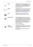
Underside, Battery lock, Notches, Battery release, latch, Docking interface
 |
View all Toshiba Tecra M2-S410 manuals
Add to My Manuals
Save this manual to your list of manuals |
Page 50 highlights
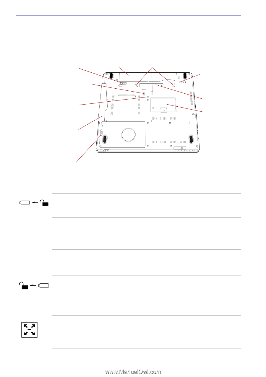
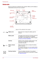
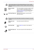
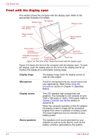
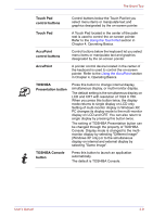
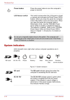
The Grand Tour Underside Figure 2-5 shows the underside of the computer. Make sure the display is closed before turning over your computer. Battery lock Battery pack Slim Select Bay lock Notches Slim Select Bay lock screw Battery release latch Docking Interface Memory module cover Slim Select Bay HDD pack cover screw Battery lock Figure 2-5 The underside of the computer Slide this lock to release the battery pack for removal. Battery pack Notches Battery release latch Docking interface The battery pack powers the computer when the AC adaptor is not connected. For detailed information on the battery pack, refer to Chapter 6, Power and Power-Up Modes. Notches on the computer engage hooks on the Advanced port Replicator III to hold the connection securely. Slide and hold this latch to release the battery pack for removal. For detailed information on removing the battery packs, refer to Chapter 6, Power and Power-Up Modes. This port enables connection of an optional Advanced port Replicator III described in Chapter 8, Optional Devices. 2-6 User's Manual
-
 1
1 -
2
-
3
-
4
-
5
-
6
-
7
-
8
-
9
-
10
-
11
-
12
-
13
-
14
-
15
-
16
-
17
-
18
-
19
-
20
-
21
-
22
-
23
-
24
-
25
-
26
-
27
-
28
-
29
-
30
-
31
-
32
-
33
-
34
-
35
-
36
-
37
-
38
-
39
-
40
-
41
-
42
-
43
-
44
-
 45
45 -
 46
46 -
 47
47 -
 48
48 -
 49
49 -
 50
50 -
 51
51 -
 52
52 -
 53
53 -
 54
54 -
 55
55 -
56
-
57
-
58
-
59
-
60
-
61
-
62
-
63
-
64
-
65
-
66
-
67
-
68
-
69
-
70
-
71
-
72
-
73
-
74
-
75
-
76
-
77
-
78
-
79
-
80
-
81
-
82
-
83
-
84
-
85
-
86
-
87
-
88
-
89
-
90
-
91
-
92
-
93
-
94
-
95
-
96
-
97
-
98
-
99
-
100
-
101
-
102
-
103
-
104
-
105
-
106
-
107
-
108
-
109
-
110
-
111
-
112
-
113
-
114
-
115
-
116
-
117
-
118
-
119
-
120
-
121
-
122
-
123
-
124
-
125
-
126
-
127
-
128
-
129
-
130
-
131
-
132
-
133
-
134
-
135
-
136
-
137
-
138
-
139
-
140
-
141
-
142
-
143
-
144
-
145
-
146
-
147
-
148
-
149
-
150
-
151
-
152
-
153
-
154
-
155
-
156
-
157
-
158
-
159
-
160
-
161
-
162
-
163
-
164
-
165
-
166
-
167
-
168
-
169
-
170
-
171
-
172
-
173
-
174
-
175
-
176
-
177
-
178
-
179
-
180
-
181
-
182
-
183
-
184
-
185
-
186
-
187
-
188
-
189
-
190
-
191
-
192
-
193
-
194
-
195
-
196
-
197
-
198
-
199
-
200
-
201
-
202
-
203
-
204
-
205
-
206
-
207
-
208
-
209
-
210
-
211
-
212
-
213
-
214
-
215
-
216
-
217
-
218
-
219
-
220
-
221
-
222
-
223
-
224
-
225
-
226
-
227
-
228
-
229
-
230
-
231
-
232
-
233
-
234
-
235
-
236
-
237
-
238
-
239
-
240
-
241
-
242
-
243
-
244
-
245
-
246
 |
 |