Troy-Bilt Horse Tiller Technical Manual
Troy-Bilt Horse Tiller Manual
 |
View all Troy-Bilt Horse Tiller manuals
Add to My Manuals
Save this manual to your list of manuals |
Troy-Bilt Horse Tiller manual content summary:
- Troy-Bilt Horse Tiller | Technical Manual - Page 1
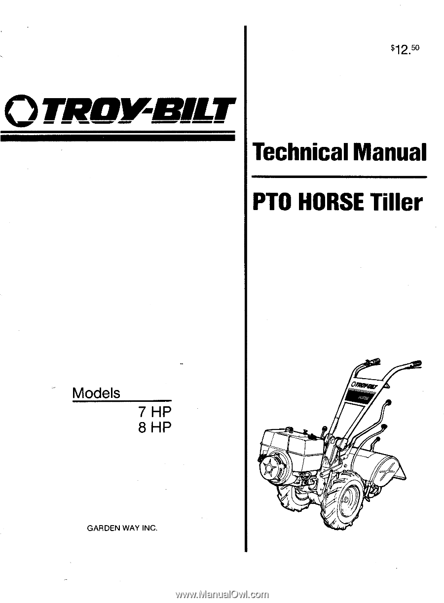
$12.50 OTP0111-113ILT Technical Manual PTO HORSE Tiller Models 7 HP 8 HP GARDEN WAY INC. a°w - Troy-Bilt Horse Tiller | Technical Manual - Page 2
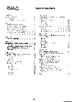
2. .'ransmission Troubleshooting 2-1 Forward and Reverse Shifting Problems 2-1 Wheel Speed Shifting Problems 2-2 Wheels and/or Tines Do Not Turn 2-3 Wheel Shaft Moves To One Side 2-4 Noise From Rear Tiller Bearing 2-4 Oil Leaks 2-5 SECTION 3. Pre-Service Inspection 3-1 SECTION - Troy-Bilt Horse Tiller | Technical Manual - Page 3
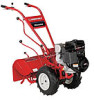
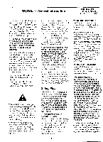
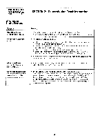
1: General Information PTO HORSE MODEL TECHNICAL MANUAL Page 1-1 4/90 • This manual provides transmission service information for the PTO HORSE Model TROY-BILT® Roto Tiller-Power Composter built by TROY-BILT Manufacturing Company, Troy, New York. Use this manual for tillers with serial numbers - Troy-Bilt Horse Tiller | Technical Manual - Page 4
Use only genuine Troy-Bilt replacement parts. Replacement parts manufactured by others could present safety hazards even though they may fit on this tiller. Quick Reference Repair Index To obtain service information for the following topics, please refer to either this Technical Manual or the Owner - Troy-Bilt Horse Tiller | Technical Manual - Page 5
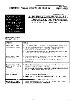
the problem. call the TROY-BILT' Tiller Technical Service Department at TOLL-FREE 1-800-833-6990. A WARNING: When servicing the machine, adjustment block, and linkages on lever. See the Owner/Operator Manual for instructions. Wheels/Tines/PTO Lever sticks in forward. • Lubricate the motor mount - Troy-Bilt Horse Tiller | Technical Manual - Page 6
PTO HORSE MODEL TECHNICAL MANUAL Page 2-2 4/90 SECTION 2: Transmission Troubleshooting Wheel Speed Shifting Problems Symptom See "Tightening the Castle Nut On the Wheel Speed Lever" in Section 7 of this manual. • Inspect the Wheel Speed Lever: ■ Lubricate the Wheel Speed Lever linkage where - Troy-Bilt Horse Tiller | Technical Manual - Page 7
SECTION 2: Transmission Troubleshooting PTO HORSE MODEL TECHNICAL MANUAL Page 2-3 4/90 Wheels and/or Tines Do Not Turn Symptom Wheels and tines won't turn even though Wheels/Tines/PTO Lever seems to work properly. Tines turn but the wheels do not turn or turn only in one speed. The Wheel Speed - Troy-Bilt Horse Tiller | Technical Manual - Page 8
Page 2-4 4/90 SECTION 2: Transmission Troubleshooting Wheels and/or Tines Do Not Turn Symptom Wheels turn but the tines do not. Remedy • Make sure the Tines/PTO Clutch Lever is engaged. • Adjust the Tines/PTO Clutch Lever. • Make sure the power unit or tiller attachment's dog clutch key is in - Troy-Bilt Horse Tiller | Technical Manual - Page 9
SECTION 2: Transmission Troubleshooting PTO HORSE MODEL TECHNICAL MANUAL Page 2-5 4/90 Oil Leaks Symptom Oil leaks from the wheel shaft oil seals. Oil leaks from the rear of the tiller attachment housing. Remedy • An oil seal is worn or damaged. Check for side-to-side and vertical play in the - Troy-Bilt Horse Tiller | Technical Manual - Page 10
PTO HORSE MODEL TECHNICAL MANUAL Page 2-6 4/90 SECTION 2: Transmission Trouleshooting Oil Oil is leaking between the power unit housing cover and the housing. • Tighten the housing cover bolts. . Replace the gasket. • A special transmission cover gasket (Part No. 9260) may be required if the - Troy-Bilt Horse Tiller | Technical Manual - Page 11
Inspection PTO HORSE MODEL TECHNICAL MANUAL Page 3-1 4/90 Before you begin your repair or maintenance procedure take a moment to perform a pre-service inspection of the following transmission parts. In doing so, you may discover additional problems that can be corrected while the tiller is in - Troy-Bilt Horse Tiller | Technical Manual - Page 12
find such play, tighten the tiller housing cover bolts. If this does not eliminate the play, a shim may need to be installed on the tiller tine shaft, as explained in Section 6 of this manual. PTO Power Unit and Tiller Attachment Drive Shaft Connection - Engage the Tines/ PTO Clutch Lever and turn - Troy-Bilt Horse Tiller | Technical Manual - Page 13
for part locations in these instructions. If only the Tiller Attachment transmission needs to be removed from the tiller, refer to the Owner/Operator Manual for instructions on how to remove the transmission when the tiller is fully assembled. A WARNING: When servicing the machine, prevent - Troy-Bilt Horse Tiller | Technical Manual - Page 14
from the wheel shaft. See the Owner/Operator Manual for instructions. Or, if the wheel is rusted on the shaft, see "Removing a Rusted Wheel" in Section 7 of this manual. Separating the Transmissions 1. Put the transmission (PTO power unit and tiller attachment assembly) on the floor, a workbench, or - Troy-Bilt Horse Tiller | Technical Manual - Page 15
the dog clutch until it fits the tiller attachment dog clutch. Note: If you put the Tines/PTO Clutch in neutral you will not have to line up the dog PTO Horse Model Owner/Operator Manual. 20. For electric start tillers only: a. Attach the battery bracket to the transmission cover and attach the two - Troy-Bilt Horse Tiller | Technical Manual - Page 16
and should release quickly from Reverse when you release the lever. Refer to the Owner/Operator Manual for information on making final adjustments to this important control lever. 27. Make sure that the transmissions for the power unit and the tiller attachment are correctly filled with gear oil. - Troy-Bilt Horse Tiller | Technical Manual - Page 17
Ii 1 PTO Power Unit Housing Cover These instructions describe how to service the PTO power unit housing cover. Use Figure 5-1 as a reference for part locations in these instructions. Removal 1. Remove the bolt (1) that holds the Tines/PTO Clutch Lever knob (2) to the Tines/PTO Clutch Lever. Then - Troy-Bilt Horse Tiller | Technical Manual - Page 18
the two rear bolts loose. 4. Reattach the tiller attachment to the PTO power unit and then reinstall the transmission assem- bly on the tiller. See Section 4 for instrucitions. 5. Refill the transmission with gear oil if it was previously drained. See the Owner/Operator Manual for instructions on - Troy-Bilt Horse Tiller | Technical Manual - Page 19
and remove the remainder of the Tines/PTO Clutch Lever assembly (6-9). Observe the part of the lever (9) that engages the dog clutch (5). If it is excessively worn or damaged, or if the customer has had difficulty engaging the tiller attachment, replace the part with a newer-style socket head screw - Troy-Bilt Horse Tiller | Technical Manual - Page 20
attachment. After removing the bearings, remove the shoulder washers (22), if so equipped. Inspection These instructions describe how to inspect vital parts on the PTO power unit drive shaft. In addition to inspecting the parts you have removed, you should also inspect any replacement parts you will - Troy-Bilt Horse Tiller | Technical Manual - Page 21
grease. Stop where the housing bore widens to accept the tiller attachment sleeve. 20. Attach the Tines/PTO Clutch Lever (2) and finger tighten the bolt (1) that holds the lever. 21. Install the PTO power unit housing cover. See the instructions in this section. 22. Install the drive shaft pulley by - Troy-Bilt Horse Tiller | Technical Manual - Page 22
HORSE MODEL TECHNICAL MANUAL in the left side of the housing will be attached to the pinion shaft. See Figure instructions describe how to inspect vital parts on the pinion shaft assembly. In addition to inspecting the parts you have removed, you should also inspect any replacement parts you will - Troy-Bilt Horse Tiller | Technical Manual - Page 23
HORSE MODEL TECHNICAL MANUAL Page 5-7 4/90 Note: Thoroughly degrease and clean all parts . Dirt or debris will prevent the O-rings from instructions in this section. Use Figure 5-4 as a reference for part locations in these instructions. 1. Attach 12 o'clock. 8. Support the assembly by inserting - Troy-Bilt Horse Tiller | Technical Manual - Page 24
describe how to service the wheel shaft assembly. For instructions on how to remove the wheel shaft without disassembling the entire PTO power unit, see "Removing the Wheel Shaft Without Disassembling the Transmission" in Section 7. Use Figure 5-7 as a reference for part locations in these - Troy-Bilt Horse Tiller | Technical Manual - Page 25
SECTION 5: PTO Power Unit Transmission PTO HORSE MODEL TECHNICAL MANUAL Page 5-9 4/90 Removal Before you can service the wheel shaft assembly, you must first remove the pinion shaft assembly. See the pinion shaft removal instructions in this section. 1. Remove the left side oil seal (1). You - Troy-Bilt Horse Tiller | Technical Manual - Page 26
describe how to service the eccentric shaft assembly. Before you can remove the eccentric shaft you must first remove the wheel shaft. See the wheel shaft removal instructions in this section. Use Figure 5-8 as a reference for part locations in these instructions. Removal 1. Remove the wheel - Troy-Bilt Horse Tiller | Technical Manual - Page 27
SECTION 5: PTO Power Unit Transmission PTO HORSE MODEL TECHNICAL MANUAL Page 5-11 4/90 1 6 7 1 + Figure 5-8: Eccentric Shaft Assembly. CA 54 4 2 housing. Make sure the shifting arm on the eccentric shaft is facing up, or at 12 o' - Troy-Bilt Horse Tiller | Technical Manual - Page 28
PTO HORSE MODEL TECHNICAL MANUAL Page 6-1 4/90 SECTION 6: Tiller Attachment Transmission This section describes the the procedures for servicing the tiller attachment transmission. A WARNING: When servicing the machine, prevent unintentional starting of the engine by disconnecting the spark - Troy-Bilt Horse Tiller | Technical Manual - Page 29
6: Tiller Attachment Transmission PTO HORSE MODEL TECHNICAL MANUAL Page 6-2 4/90 3. Remove the dog clutch and the key (3). 4. Remove the dog clutch spring (4). 5. Remove the dog clutch shim (5). 6. Remove the second (external) snap ring (2a). 7. Remove the three bolts (6) that secure the rear - Troy-Bilt Horse Tiller | Technical Manual - Page 30
in this section. Tiller Tine Shaft Assembly These instructions describe how to remove, inspect, and install the tiller attachment's tine shaft assembly. Use Figure 6-2 as a reference for part locations in these instructions. Removal You will have to disassemble the tiller tine shaft assembly to - Troy-Bilt Horse Tiller | Technical Manual - Page 31
SECTION 6: Tiller Attachment Transmission PTO HORSE MODEL TECHNICAL MANUAL Page 6-4 4/90 the Owner/Operator Manual for instructions on how to remove the bolo tine holders. 1. Remove the five bolts (1) and nylon washers (2), if any, that secure the tiller housing cover (3). Discard the washers. - Troy-Bilt Horse Tiller | Technical Manual - Page 32
PTO HORSE MODEL TECHNICAL MANUAL Page 6-5 4/90 SECTION 6: Tiller Attachment Transmission b. Force the shaft down. This will dislodge one bearing (7). Also remove the washer (9), if so equipped. 10. Turn the shaft assembly 180 degrees and use the arbor press to dislodge the - Troy-Bilt Horse Tiller | Technical Manual - Page 33
Attachment Transmission PTO HORSE MODEL TECHNICAL MANUAL Page 6-6 4/90 are not sufficient, use two .030" gaskets, etc. until the shaft is shimmed correctly. Note: No more than .060" in total gasket thickness should be needed to correctly shim the tine shaft. Call the Troy-Bilt Technical Service - Troy-Bilt Horse Tiller | Technical Manual - Page 34
Tines/PTO /Clutch Lever Assembly In early model PTO Horse models, a ball bearing assembly on the Tines/PTO Clutch Shaft functioned as the contact piece that moved the PTO power unit dog clutch to engage the tiller attachment . WARNING: When servicing the machine, prevent unintentional starting - Troy-Bilt Horse Tiller | Technical Manual - Page 35
the rear of housing. The screw is properly seated if the clutch moves back and forth with each turn of the eccentric shaft. 8. Tighten the hex nut/bushing securely with a wrench. 9. Fill the dog clutch cavity with grease. Stop where the housing bore widens to accept the tiller attachment sleeve - Troy-Bilt Horse Tiller | Technical Manual - Page 36
PTO HORSE MODEL TECHNICAL MANUAL Page 7-3 4/90 SECTION 7: Special Repairs and Procedures 11 10 14 16 / hold the old shaft and hammer. As you tap the drive shaft out, the key in the shaft will also remove the right-side bushing, snap ring, shim(s), and oil seal. 8. Using a long punch - Troy-Bilt Horse Tiller | Technical Manual - Page 37
HORSE MODEL TECHNICAL MANUAL Page 7-4 4/90 Note: If necessary, you can remove the power unit housing cover to move the gear and clutch by hand. 8. Complete the installation of the wheel shaft. See Section 5 of this manual the Wheel Speed Lever Follow these instructions to tighten the castle nut ( - Troy-Bilt Horse Tiller | Technical Manual - Page 38
. . .5-1 Tiller tine shaft Installing. . .6-5 Removing. . .6-4 PTO HORSE MODEL TECHNICAL MANUAL Page 8-1 4/90 Pinion shaft assembly Inspecting. ..5-6 Installing. . .5-7 Removing. . .5-5 Pre-service inspection. . .3-1 PTO power unit Servicing . . .5-1 PTO power unit/tiller attachment Attaching - Troy-Bilt Horse Tiller | Technical Manual - Page 39
OT_Rownar TROY-BILT MANUFACTURING CO., 102nd Street & 9th Ave., Troy, New York 12180 Call Toll-Free: 1-800-833-6990 GARDEN WAY CANADA, INC., 1515• Matheson Blvd., Unit B11, Mississauga, Ontario L4W Maritime Provinces call Toll-Free: 1-800-387-3316 MN1330490 Printed in U.S.A. c,1990 Garden Way Inc.
-
 1
1 -
 2
2 -
 3
3 -
 4
4 -
 5
5 -
 6
6 -
 7
7 -
8
-
9
-
10
-
11
-
12
-
13
-
14
-
15
-
16
-
17
-
18
-
19
-
20
-
21
-
22
-
23
-
24
-
25
-
26
-
27
-
28
-
29
-
30
-
31
-
32
-
33
-
34
-
35
-
36
-
37
-
38
-
39
 |
 |
$12.
50
OTP0111-113ILT
Technical
Manual
PTO
HORSE
Tiller
Models
7
HP
8
HP
GARDEN
WAY
INC.
a°w