Troy-Bilt Horse Tiller Technical Manual - Page 25
Removal, Inspection, Installation
 |
View all Troy-Bilt Horse Tiller manuals
Add to My Manuals
Save this manual to your list of manuals |
Page 25 highlights
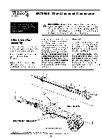
SECTION 5: PTO Power Unit Transmission PTO HORSE MODEL TECHNICAL MANUAL Page 5-9 4/90 Removal Before you can service the wheel shaft assembly, you must first remove the pinion shaft assembly. See the pinion shaft removal instructions in this section. 1. Remove the left side oil seal (1). You can remove the seal with a screwdriver and hammer by tapping in at an angle and prying against the the transmission case (if necessary, use two screwdrivers positioned at opposite sides of the seal). Note: Be careful not to damage the wheel shaft with the screwdriver(s) while prying. 2. Remove and discard the left side (external) snap ring (2) that retains the wheel shaft (5) inside the housing. 3. Use a magnet to remove the shim(s) (3). Discard the shim(s). 4. Shift the eccentric lever (12) into neutral. The clutch and gears must be disengaged. 5. Using a rubber mallet, tap the wheel shaft to the right while you slowly turn the fast speed (smaller) gear (4). The object is to line up the key (14) in the shaft with the keyway in the fast speed gear. This is a trial and error procedure. Keep trying until you feel the key in the shaft begin to advance through the fast speed gear. After the key begins to pass through the gear, continue until you remove the wheel shaft (5) along with the right side bronze bushing (8), oil seal (1), snap ring (6), and shims (7). Discard the bushing, oil seal, snap ring, and shims(s). 6. Check that the hi-pro key (14) is still attached to the wheel shaft. If it is not, retrieve it from inside the housing. 7. Lift the stow speed (larger) gear (9), fast speed gear, clutch (10), and three clutch guide pins (11) out of the housing. 8. Remove and discard the bronze bushing (13) from the left side of the housing. Use an old wheel shaft inserted from the right-hand side to drive the bushing out. Inspection These instructions describe how to inspect vital parts on the wheel shaft assembly. In addition to inspecting the parts you have removed, you should also inspect any replacement parts you will use. Note: Thoroughly degrease and clean all parts before inspection. Wheel Shaft - • If the wheel shaft is scored or pitted around the oil seal areas, you may be able to relocate the oil seals further out, or in, in order to avoid the damaged area. • If there is corrosion around the oil seal areas, try using an emery cloth to clean the area. If the wheel shaft is badly scored or pitted around the oil seal areas, discard the wheel shaft. • If the seal area is excessively worn, discard the wheel shaft. • Examine both ends of the wheel shaft for burrs or rough edges that could prevent the shaft from passing through the gears or clutch. Use a file or emery cloth to remove any rough spots. • If the outside edges of the snap ring grooves are rounded, you will have to discard the wheel shaft as these edges bear the force of the snap rings. If the grooves have expanded you may be able to use shims to take up the slack. If not, discard the wheel shaft. • If the area around the keyway 2.5". has bubbled due to key movement, discard the wheel shaft. See "Testing for a Bubbled Wheel Shaft" in Section 7. Fast and Slow Speed Gears - • If there are any broken or excessively worn teeth, discard the gear. • If the clutch dogs have worn a groove more than 1/4 through the wall of the gear (usually due to speed shifting), discard the gear. Clutch - • If the clutch dogs are excessively rounded, discard the clutch. • If any clutch dogs are missing, discard the clutch. • If the keyway is damaged, you may be able to straighten it with a file. Otherwise, discard the clutch. Note: If the keyway is too wide, the wheel shaft is more likely to bubble and you may need to replace the wheel shaft soon afterwards. Gear Shifting Guide Pins - Make sure the guide pins are absolutely straight. If a pin is even slightly bent, discard it. Installation Before you install the wheel shaft assembly, the eccentric shaft assembly must first be installed. See the eccentric shaft installation instructions in this section. Use Figure 5-7 as a reference for part locations in these instructions. 1. Before installing the wheel shaft: • Make sure the hi-pro key (14) is firmly seated in the keyway. • Make sure the clutch (10) and fast speed gear (4) pass freely over the hi-pro key in the wheel shaft. If there is any binding,
-
 1
1 -
2
-
3
-
4
-
5
-
6
-
7
-
8
-
9
-
10
-
11
-
12
-
13
-
14
-
15
-
16
-
17
-
18
-
19
-
 20
20 -
 21
21 -
 22
22 -
 23
23 -
 24
24 -
 25
25 -
 26
26 -
 27
27 -
 28
28 -
 29
29 -
 30
30 -
31
-
32
-
33
-
34
-
35
-
36
-
37
-
38
-
39
 |
 |
