Troy-Bilt Horse Tiller Technical Manual - Page 17
Power, Transmission
 |
View all Troy-Bilt Horse Tiller manuals
Add to My Manuals
Save this manual to your list of manuals |
Page 17 highlights
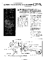
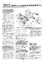
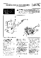
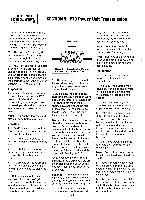
SECTION 5: PTO Power Unit Transmission PTO HORSE MODEL TECHNICAL MANUAL Page 5-1 4/90 The following subsections explain how to service various items on the PTO Horse Model Power Unit Transmission. A WARNING: When servicing the machine, prevent unintentional starting of the engine by disconnecting the spark plug wire and keeping the wire away from the spark plug. Place the engine throttle control in the OFF position and shift the Wheels/Tines/PTO Drive Lever into NEUTRAL. 2 4 (.51 2 1163--.48? 4 -20 / 5 34 1 6 10 re) 4 - 11 12 -0 0 8 0 7 Figure 5-1: PTO Power Unit Housing Cover. Ii 1 PTO Power Unit Housing Cover These instructions describe how to service the PTO power unit housing cover. Use Figure 5-1 as a reference for part locations in these instructions. Removal 1. Remove the bolt (1) that holds the Tines/PTO Clutch Lever knob (2) to the Tines/PTO Clutch Lever. Then remove the knob. 2. Remove the two bolts (3) and washers (if present) from the top of the shift lever bracket (4). 3. Remove the bolt (5), lock- washer (if present), and the washer (6) from the side of the shift lever bracket. 4. Remove the shift lever bracket. 5. Remove the locknut (7) that holds the speed shift lever connecting rod swivel (see inset) (8) to the eccentric lever (9). 6. Separate the tiller attachment from the PTO power unit. See "Separating the PTO Power Unit and Tiller Attachment Transmission Assembly" in Section 4 for instructions. 7. Set the PTO power unit on a bench or other comfortable work area. 117 8. If necessary, drain the transmission gear oil from the PTO power unit by loosening and removing the oil drain plug, which is located below the wheel shaft on the left side of the transmission housing. After the oil is drained, apply a coating of non-hardening gasket sealer on the threads and reinstall the oil plug. If the plug is damaged, use a new plug. 9. Remove the remaining two bolts (3) and lockwashers (if present) that secure the PTO power unit housing cover (11), and remove the cover. 10. Discard the gasket (12).
-
 1
1 -
2
-
3
-
4
-
5
-
6
-
7
-
8
-
9
-
10
-
11
-
 12
12 -
 13
13 -
 14
14 -
 15
15 -
 16
16 -
 17
17 -
 18
18 -
 19
19 -
 20
20 -
 21
21 -
 22
22 -
23
-
24
-
25
-
26
-
27
-
28
-
29
-
30
-
31
-
32
-
33
-
34
-
35
-
36
-
37
-
38
-
39
 |
 |
