Troy-Bilt Horse Tiller Technical Manual - Page 29
attachment.
 |
View all Troy-Bilt Horse Tiller manuals
Add to My Manuals
Save this manual to your list of manuals |
Page 29 highlights
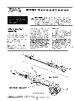
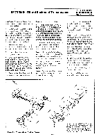
SECTION 6: Tiller Attachment Transmission PTO HORSE MODEL TECHNICAL MANUAL Page 6-2 4/90 3. Remove the dog clutch and the key (3). 4. Remove the dog clutch spring (4). 5. Remove the dog clutch shim (5). 6. Remove the second (external) snap ring (2a). 7. Remove the three bolts (6) that secure the rear bearing cap (7), also removing and discarding the nylon washers (8), if any. Have a pan ready to catch the gear oil that will pour out when you remove the rear bearing cap in the next step. 8. Remove the rear bearing cap and the gasket (9). Discard the gasket. 9. Use a rubber hammer to tap the forward end of the drive shaft (11) toward the rear of the housing. As you are tapping the shaft, catch the bearing cap shims (10) and bearing cup (12) at the rear of the shaft. Discard the shims. Drive the shaft out until the drive shaft worm clears the housing. Leave the drive shaft in this position until you complete step 10. Note: Keep each bearing cup paired with its bearing if you intend to reuse them. Each bearing cup wears differently according to its bearing. 10. Remove the tiller tine shaft assembly. See the tiller tine shaft removal instructions in this section. You must remove the tiller tine shaft before you can completely remove the tiller drive shaft. 11. Remove the tiller drive shaft. 12. Remove the oil seal (13) by placing a long bar through the rear of the housing and tapping the seal out. Take care not to damage the bear- ing cup (14), snap ring (15), or tiller housing. 13. Remove the (internal) snap ring (15) that retains the front bearing cup (14) using a pair of snap ring pliers. 14. Remove the bearing cup. If the bearing cup resists, insert an old tiller drive shaft into the back of the transmission housing and use its bearing to nudge the bearing cup forward. It is not recommended that you use a good drive shaft for this. Note: Remember to keep track of which bearing cups go with which bearings. You will need to assemble them in the same pairs. 15. After the drive shaft is removed and you have an empty tiller housing, thoroughly degrease and clean the inside and outside of the housing. 16. The drive shaft bearings (16) are pressed-on and can be removed (if necessary) with an arbor press and a bearing puller attachment. On the welded worm style drive shaft only, remove the shoulder washer (17) after removing the front bearing. Inspection These instructions describe how to inspect parts on the tiller drive shaft. In addition to inspecting the parts you have removed from the tiller housing, you should also inspect any replacement parts you will use. Note: Thoroughly degrease and clean all parts before inspection. Drive Shaft - • The drive shaft should not be scored, pitted, or corroded where the oil seal is located. If the shaft is lightly corroded, you might be able to clean it using an emery cloth. If the shaft is slightly scored or pitted you might be able to adjust the position of the front seal so that it is seated on a smooth part of the shaft. If the drive shaft is excessively pitted or corroded, especially in the area where the oil seal seats, discard the drive shaft. • Inspect the drive shaft for burrs or rough spots at the ends of the shaft and where the bearings fit on the shaft. Use a file or emery cloth to remove rough spots or burrs, being careful not to remove too much metal where the bearings will be seated. (Doing so will prevent the proper fit of the bearings on the shaft.) • The keyway should be just wide enough for the key to fit. If the keyway expands and becomes too wide; discard the tiller drive shaft. • The two snap ring grooves should be just wide enough to fit the snap ring. If the groove becomes too wide, you will have to discard the tiller drive shaft. Also, the forward-facing edges of the grooves should not be rounded off; these are the edges that bear the force of the snap ring. If this edge is rounded you must discard the tiller drive shaft. Worm - The worm should not be excessively worn. Since only the middle of the worm is in contact with the bronze worm gear on the tiller tine shaft, you can compare the end of the worm (on the tiller drive shaft) with the middle. If the width of the teeth in the middle is half or less than the width of the teeth at the ends, discard the tiller drive shaft. Also, inspect the worm for heat damage. If the worm has a bluish color then proper lubrication has not been maintained; discard the tiller drive shaft. Bearings - If the bearing has a bluish color then proper lubrica-
-
 1
1 -
2
-
3
-
4
-
5
-
6
-
7
-
8
-
9
-
10
-
11
-
12
-
13
-
14
-
15
-
16
-
17
-
18
-
19
-
20
-
21
-
22
-
23
-
 24
24 -
 25
25 -
 26
26 -
 27
27 -
 28
28 -
 29
29 -
 30
30 -
 31
31 -
 32
32 -
 33
33 -
 34
34 -
35
-
36
-
37
-
38
-
39
 |
 |
