Troy-Bilt Horse Tiller Technical Manual - Page 37
Identifying, Bubbled, Wheel, Shaft, Tightening, Castle, Speed, Lever
 |
View all Troy-Bilt Horse Tiller manuals
Add to My Manuals
Save this manual to your list of manuals |
Page 37 highlights
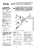
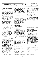
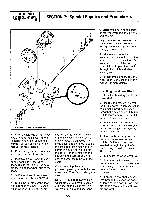
SECTION 7: Special Repairs and Procedures PTO HORSE MODEL TECHNICAL MANUAL Page 7-4 4/90 Note: If necessary, you can remove the power unit housing cover to move the gear and clutch by hand. 8. Complete the installation of the wheel shaft. See Section 5 of this manual for more information. Identifying a Bubbled Wheel Shaft A wheel shaft is bubbled when the metal around the keyway raises or swells slightly. This weakening of the metal is due to excessive pressure being exerted by the clutch on the hi-pro key to turn the wheels. This is often caused by improper shifting or by the wheels striking an object that abruptly cause them to stop turning. A bubbled wheel shaft should be discarded and replaced with a new one. Testing for a Bubbled Wheel Shaft Disconnect the linkage from the eccentric lever and work the eccentric lever by hand. If the lever is difficult to move the wheel shaft may be bubbled. Tightening the Castle Nut On the Wheel Speed Lever Follow these instructions to tighten the castle nut (see Figure 7-3). The castle nut holds the Wheel Speed Lever on the transmission. 1. Remove the spring pin from the castle nut. 2. Tighten the castle nut. When the castle nut is properly tightened, it should require a force of 13-17 lbs. to move the Wheel Speed Lever. 3. Align the nearest slot in the castle nut with the hole in the mounting stud. Make sure that the castle nut is still tight and that the Wheel Speed Lever moves freely. 4. Install a new spring pin until it is flush with the top of the slotted nut. \ Spring Pin Castle Nut Figure 7-3: The Castle Nut.
-
 1
1 -
2
-
3
-
4
-
5
-
6
-
7
-
8
-
9
-
10
-
11
-
12
-
13
-
14
-
15
-
16
-
17
-
18
-
19
-
20
-
21
-
22
-
23
-
24
-
25
-
26
-
27
-
28
-
29
-
30
-
31
-
 32
32 -
 33
33 -
 34
34 -
 35
35 -
 36
36 -
 37
37 -
 38
38 -
 39
39
 |
 |
