Troy-Bilt Horse Tiller Technical Manual - Page 16
Troy-Bilt Horse Tiller Manual
 |
View all Troy-Bilt Horse Tiller manuals
Add to My Manuals
Save this manual to your list of manuals |
Page 16 highlights
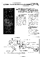
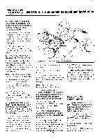
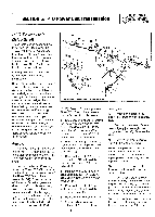
PTO HORSE MODEL TECHNICAL MANUAL SECTION 4: Transmission Removal and Installation Page 4-4 4/90 c. Connect the recharging wire that leads from the keyswitch wire harness to the engine. d. Connect the red starter cable to the starter motor on the engine. e. Install the battery as described in the Owner/Operator Manual. 21. Loosen the two bolts (14) that secure the Tines/PTO Clutch Lever detent plate (15) to the shift lever bracket. 22. Loosen the bolt (16) that secures the Tines/PTO Clutch Lever (13) to the eccentric shaft. 23. Move the lever until it is inside one of the two detent slots in the detent plate. Then tighten the bolt (16) that holds the lever to the shaft. A correctly installed lever will have to be pulled out before you are able to slide the lever to the other detent slot. 24. With the lever in the ENGAGE position (both dog clutches must be fully engaged), slide the detent plate to the rear of the housing against the lever until it can go no further. Move the plate forward 1/16 of an inch and tighten the two detent plate mounting bolts (14). You should feel some lever play in either the ENGAGE or DISENGAGE position. 25. Install the drive belt on the engine and transmission pulleys and adjust the belt tension according to the directions found in the Owner/Operator Manual. 26. Check the operation of the Wheels/Tines/PTO Lever by shifting it into Forward, then Neutral and Reverse. The lever should hold properly in Forward and should release quickly from Reverse when you release the lever. Refer to the Owner/Operator Manual for information on making final adjustments to this important control lever. 27. Make sure that the transmissions for the power unit and the tiller attachment are correctly filled with gear oil.
-
 1
1 -
2
-
3
-
4
-
5
-
6
-
7
-
8
-
9
-
10
-
 11
11 -
 12
12 -
 13
13 -
 14
14 -
 15
15 -
 16
16 -
 17
17 -
 18
18 -
 19
19 -
 20
20 -
 21
21 -
22
-
23
-
24
-
25
-
26
-
27
-
28
-
29
-
30
-
31
-
32
-
33
-
34
-
35
-
36
-
37
-
38
-
39
 |
 |
