Troy-Bilt Horse Tiller Technical Manual - Page 36
Installing, Wheel, Shaft
 |
View all Troy-Bilt Horse Tiller manuals
Add to My Manuals
Save this manual to your list of manuals |
Page 36 highlights
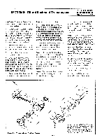
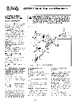
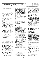
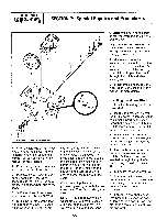
PTO HORSE MODEL TECHNICAL MANUAL Page 7-3 4/90 SECTION 7: Special Repairs and Procedures 11 10 14 16 / 15 12 13 XI 423 Figure 7-2: Wheel Shaft Assembly. 3. From the left side of the wheel shaft, remove the oil seal (1), the (external) snap ring (2), and the shim(s) (3). See Section 5 in this manual for more details. 4. From the right side of the wheel shaft, remove the oil seal (1). 5. Insert a screwdriver in the hole on the right side of the wheel shaft. This is the hole for the spirol pin that holds the wheel hub to the shaft. 6. Shift the Wheel Speed Lever so that the clutch is in NEUTRAL. 7. Strike the left side of the shaft with a rubber hammer. The shaft will move inward until the hi-pro key (14) on the shaft hits the side of the fast speed wheel gear (4). Slowly rotate the shaft with the screwdriver and continue to strike the left side of the shaft with the hammer. You are trying to align the key (14) in the shaft with the keyway in the fast speed wheel gear to permit the removal of the shaft. Continue hitting the shaft until you feel it passing through the fast speed gear. Then finish driving the shaft out. Note: If you had to saw the left wrieel off, you will have to use an old wheel shaft as a driver. This will require you to find someone to assist you in turning the screwdriver while you hold the old shaft and hammer. As you tap the drive shaft out, the key in the shaft will also remove the right-side bushing, snap ring, shim(s), and oil seal. 8. Using a long punch inserted from the right side of the housing, remove the bronze bushing (13) from the left side of the housing. You will have to pass the punch through the clutch and wheel speed gears. 9. Disassemble and inspect the wheel shaft. See Section 5 in this manual for more details. Installing the Wheel Shaft 1. Install a hi-pro key (14) in the wheel shaft. 2. Inspect the new wheel shaft for burrs or other rough spots that could make inserting the shaft through the gears and clutch difficult. If necessary, use emery cloth to remove any rough spots. 3. Pull the eccentric lever (12) back and wedge it. This releases the eccentric shaft (15) pressure on the clutch (10). 4. Line up the keyways on the fast speed wheel gear (4) and clutch (10). Use a screwdriver inserted through the right side of the housing to position them at 12 o'clock. 5. Lubricate the wheel shaft (5). 6. With the key in the wheel shaft positioned at 12 o'clock, insert the shaft through the right side. Do not use force; do not use a hammer. 7. Pass the wheel shaft and its key through the fast speed gear, clutch, and slow speed gear. This may take a few attempts until you are successful. '34
-
 1
1 -
2
-
3
-
4
-
5
-
6
-
7
-
8
-
9
-
10
-
11
-
12
-
13
-
14
-
15
-
16
-
17
-
18
-
19
-
20
-
21
-
22
-
23
-
24
-
25
-
26
-
27
-
28
-
29
-
30
-
 31
31 -
 32
32 -
 33
33 -
 34
34 -
 35
35 -
 36
36 -
 37
37 -
 38
38 -
 39
39
 |
 |
