Troy-Bilt Horse Tiller Technical Manual - Page 18
Inspection, Installation, Neutral, Plunger, Assembly
 |
View all Troy-Bilt Horse Tiller manuals
Add to My Manuals
Save this manual to your list of manuals |
Page 18 highlights
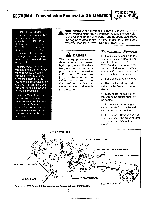
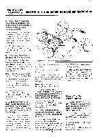
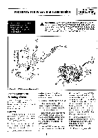
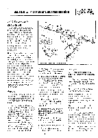
PTO HORSE MODEL TECHNICAL MANUAL Page 5-2 4/90 SECTION 5: PTO Power Unit Transmission Inspection These instructions describe how to inspect vital parts on the PTO power unit housing cover. In addition to inspecting the parts you have removed, you should also inspect any replacement parts. Note: Thoroughly degrease and clean all parts before inspection. Plunger Bolt - You must replace the neutral plunger assembly if it is frozen (penetrating oil will sometimes free a frozen bolt) or if the plunger bolt (13) has snapped off. To determine if the plunger bolt is frozen, perform the following test: 1. Loosen the hex jam nut (14). 2. Gently tighten the plunger locking bolt (15) until it stops, then add a 1/4 turn to lock it. 3. Loosen the flange locknut (16). 4. Loosen the plunger bolt (13). If you cannot loosen the bolt or if the bolt snaps off, replace the neutral plunger assembly with a new one. If the plunger bolt is not frozen on the plunger, restore the plunger assembly to its previous settings by reversing steps 1, 2 and 3. Cover - Inspect the cover for cracks. Also, make sure the threads in the handlebar mounting base are not damaged. Installation 1. Affix the gasket (12) to the cover. 2. Start the four bolts (3) and the lockwashers (if present) in the cover. 3. Tighten the two forward bolts but leave the two rear bolts loose. 4. Reattach the tiller attachment to the PTO power unit and then reinstall the transmission assem- bly on the tiller. See Section 4 for instrucitions. 5. Refill the transmission with gear oil if it was previously drained. See the Owner/Operator Manual for instructions on how to refill the transmission with oil. Neutral Plunger Assembly You would disassemble the PTO power unit housing cover if you found the neutral plunger assembly to be frozen or if the bolt snapped off. Disassembly 1. Place the housing cover on an arbor press and press down on the neutral plunger bolt (13). 2. Loosen the hex jam nut (14) then loosen the plunger locking bolt (15) until it clears the groove in the neutral plunger (17). 3. Let the arbor press up. 4. Remove the spring (18). Note: If you are servicing an 8 HP Kohler engine you may want to discard the spring and install a new one if the same spring has been in use for several years. 5. If you are installing a new plunger assembly, discard the old plunger, clip ring (19), flange nut (16), and neutral plunger bolt (13). Assembly 1. Use a hammer to seat the clip ring (19) in the groove of the neutral plunger (17). 2. Thread the flange nut (16) onto the plunger bolt (13) about three quarters of the way. 3. Apply a coating of nickelbased anti-locking compound to the threads of the plunger bolt. 4. Lubricate the inside threads of the neutral plunger (17). 1 5. Thread the plunger bolt (13) and the attached flanged nut into the neutral plunger. 6. Slip the spring (18) on the neutral plunger. 7. Apply a coating of nickelbased anti-locking compound on the bottom of the neutral plunger and insert the neutral plunger into the housing cover. 8. Place the housing cover on an arbor press. 9. Turn the plunger locking bolt (15) until it is finger tight and you feel it strike the neutral plunger. Then maintain very light pressure on the bolt with a wrench. 10. Slowly press the plunger assembly down. When the groove in the neutral plunger reaches the plunger locking bolt, the pressure on the bolt will be relieved. 11. Tighten the plunger locking bolt until it is seated and then back it off 1/2 turn. 12. Release the arbor press pressure from the plunger assembly. 13. Hold the plunger locking bolt in place and tighten the hex jam nut (14). 14. Adjust the plunger assembly for proper reverse action by referring to the adjustment instructions in the Owner/Operator Manual.
-
 1
1 -
2
-
3
-
4
-
5
-
6
-
7
-
8
-
9
-
10
-
11
-
12
-
 13
13 -
 14
14 -
 15
15 -
 16
16 -
 17
17 -
 18
18 -
 19
19 -
 20
20 -
 21
21 -
 22
22 -
 23
23 -
24
-
25
-
26
-
27
-
28
-
29
-
30
-
31
-
32
-
33
-
34
-
35
-
36
-
37
-
38
-
39
 |
 |
