Troy-Bilt Horse Tiller Technical Manual - Page 31
Owner/Operator
 |
View all Troy-Bilt Horse Tiller manuals
Add to My Manuals
Save this manual to your list of manuals |
Page 31 highlights
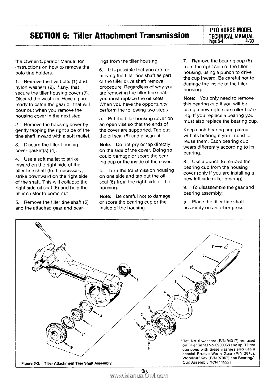
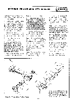
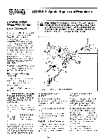
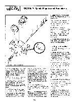
SECTION 6: Tiller Attachment Transmission PTO HORSE MODEL TECHNICAL MANUAL Page 6-4 4/90 the Owner/Operator Manual for instructions on how to remove the bolo tine holders. 1. Remove the five bolts (1) and nylon washers (2), if any, that secure the tiller housing cover (3). Discard the washers. Have a pan ready to catch the gear oil that will pour out when you remove the housing cover in the next step. 2. Remove the housing cover by gently tapping the right side of the tine shaft inward with a soft mallet. 3. Discard the tiller housing cover gasket(s) (4). 4. Use a soft mallet to strike inward on the right side of the tiller tine shaft (5). If necessary, strike downward on the right side of the shaft. This will collapse the right side oil seal (6) and help the tiller cluster to come out. 5. Remove the tiller tine shaft (5) and the attached gear and bear- ings from the tiller housing. 6. It is possible that you are removing the tiller tine shaft as part of the tiller drive shaft removal procedure. Regardless of why you are removing the tiller tine shaft, you must replace the oil seats. When you have the opportunity, perform the following two steps. a. Put the tiller housing cover on an open vise so that the ends of the cover are supported. Tap out the oil seal (6) and discard it. Note: Do not pry or tap directly on the side of the cover. Doing so could damage or score the bearing cup or the inside of the cover. b. Turn the transmission housing on one side and tap out the oil seal (6) from the right side of the housing. Note: Be careful not to damage or score the bearing cup or the inside of the housing. 7. Remove the bearing cup (8) from the right side of the tiller housing, using a punch to drive the cup inward. Be careful not to damage the inside of the tiller housing. Note: You only need to remove this bearing cup if you will be using a new right side roller bearing. If you replace a bearing you must also replace the bearing cup. Keep each bearing cup paired with its bearing if you intend to reuse them. Each bearing cup wears differently according to its bearing. 8. Use a punch to remove the bearing cup from the housing cover (only if you are installing a new left side roller bearing). 9. To disassemble the gear and bearing assembly: a. Place the tiller tine shaft assembly on an arbor press. „.. 10 Figure 6-2: Tiller Attachment Tine Shaft Assembly. 5 7 4 2 1 \ S. St *Ref. No. 9 washers (P/N 94017) are used on Tiller Serial No.0900038 and up. Tillers equipped with these washers also use a special Bronze Worm Gear (P/N 2675), Woodruff Key (P/N 97067) and Bearing/- Cup Assembly (P/N 11522).
-
 1
1 -
2
-
3
-
4
-
5
-
6
-
7
-
8
-
9
-
10
-
11
-
12
-
13
-
14
-
15
-
16
-
17
-
18
-
19
-
20
-
21
-
22
-
23
-
24
-
25
-
 26
26 -
 27
27 -
 28
28 -
 29
29 -
 30
30 -
 31
31 -
 32
32 -
 33
33 -
 34
34 -
 35
35 -
 36
36 -
37
-
38
-
39
 |
 |