Troy-Bilt Horse Tiller Technical Manual - Page 24
Wheel, Shaft, Assembly
 |
View all Troy-Bilt Horse Tiller manuals
Add to My Manuals
Save this manual to your list of manuals |
Page 24 highlights
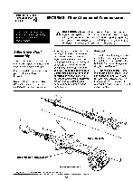
PTO HORSE MODEL TECHNICAL MANUAL Page 5-8 4/90 SECTION 5: PTO Power Unit Transmission thickness as the washer (8). Using a shim that is the same thickness as the washer will prevent any warping of the washer. 11. Using a mallet, install a bearing (7) flush with the right side housing bore. Then use the pinion bearing retaining plug (2) as a driver and seat the bearing, washer, and shim flush against the fast speed pinion gear. 12. Make sure the fast and slow speed pinion gears are flush against the worm gear. 13. Make sure the bearings are flush against their respective gears. 14. Line up the spirol pin hole on the right side retaining plug with the hole in the housing. 15. Center the worm gear. Use the drive shaft opening at the front of the PTO power unit to sight and center the gear. If the gear is not centered, tap the appropriate retaining plug inward until the gear is centered (hold the opposite plug firmly in place when driving a plug inward). 16. Repeat the previous two steps until the worm gear is centered as you view it through the opening in the front of the PTO power unit. 17. With the worm gear centered, push inward on the two retaining plugs and check to see if the spirol holes in the plugs and the housing are aligned. If a plug is not seated deeply enough, tap it in until the holes are aligned. If a plug is seated too deeply, remove it and insert one or more shims (4) until the holes are aligned. 18. Install O-rings (3) on each plug (2). 19. Use #30 weight oil to lubricate the O-rings and insert the plugs on each side. 11 4 10 14 as 1 6 1 8 16 15 12 13 3 2 1 Figure 5-7: Wheel Shaft Assembly. 20. Install the spirol pins (1) on each side. 21. With the wheel drive clutch in neutral, try to spin the bronze worm gear. It should turn easily, driving the two cast iron wheel gears as it turns. if the gear does not spin freely, strike the plugs (2) inward with a rubber hammer. This should free-up the pinion shaft assembly. If the gear still does not spin freely, it is shimmed too tightly. Wheel Shaft Assembly These instructions describe how to service the wheel shaft assembly. For instructions on how to remove the wheel shaft without disassembling the entire PTO power unit, see "Removing the Wheel Shaft Without Disassembling the Transmission" in Section 7. Use Figure 5-7 as a reference for part locations in these instructions.
-
 1
1 -
2
-
3
-
4
-
5
-
6
-
7
-
8
-
9
-
10
-
11
-
12
-
13
-
14
-
15
-
16
-
17
-
18
-
 19
19 -
 20
20 -
 21
21 -
 22
22 -
 23
23 -
 24
24 -
 25
25 -
 26
26 -
 27
27 -
 28
28 -
 29
29 -
30
-
31
-
32
-
33
-
34
-
35
-
36
-
37
-
38
-
39
 |
 |
