Troy-Bilt Horse Tiller Technical Manual - Page 35
Removing, Rusted, Wheel, Shaft, Without, Disassembling, Transmission
 |
View all Troy-Bilt Horse Tiller manuals
Add to My Manuals
Save this manual to your list of manuals |
Page 35 highlights
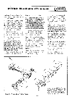
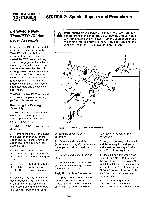
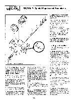
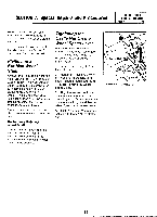
SECTION 7: Special Repairs and Procedures PTO HORSE MODEL TECHNICAL MANUAL Page 7-2 4/90 dog clutch in the center of the hole. 5. Apply a thin coating of grease to the socket head screw (12) on the eccentric shaft assembly. Then insert the assembly into the hole. Hold the assembly so that the socket head screw is at 12 o'clock. 6. Using your fingers only, gently thread the eccentric shaft hex nut/bushing (7) until the hex nut is snug against the power unit housing. The hex nut/bushing should turn freely at all times until the nut is against the housing. Do not use force; you can damage the eccentric shaft or socket head screw. If necessary, back the nut off a few turns and rotate the eccentric shaft a fraction of a turn. Then try to thread the nut inward again. 7. Make sure that you have properly seated the screw head in the clutch groove. Rotate the eccentric shaft back and forth while looking through the rear of housing. The screw is properly seated if the clutch moves back and forth with each turn of the eccentric shaft. 8. Tighten the hex nut/bushing securely with a wrench. 9. Fill the dog clutch cavity with grease. Stop where the housing bore widens to accept the tiller attachment sleeve. 10. Attach the clutch lever (3) and finger tighten the bolt (6) that holds the clutch lever. 11. Install the detent plate (5) and loosely install the two bolts (4) that hold the detent plate; do not tighten the bolts yet. 12. Install the clutch lever knob (2) and the bolt (1) on the clutch lever. 13. Move the lever until it is inside one of the two detent slots cut into the detent plate. Then tighten the bolt that holds the lever. A correctly installed lever will have to be pulled out before being able to slide it over to the other detent stop. 14. With the lever in the ENGAGE position, slide the detent plate to the rear of the housing against the lever until it can go no further. Move the plate forward 1/16 of an inch and tighten the two detent-plate mounting screws. You should feel some lever play in either the ENGAGE or DISENGAGE position. Removing a Rusted Wheel If you need to remove the wheel shaft and the left wheel or both wheels are rusted to the shaft, follow these instructions. If only the right wheel is rusted to the wheel shaft, you can still remove the wheel shaft by following the instructions in Section 5 of this manual. Once the wheel shaft is off you can soak the rusted wheel(s) in a penetrating lubricant until you can remove it. 1. Remove the roll pin that holds the wheel to the wheel shaft. If the pin does not come out smoothly, tap it out using another pin as a driver. It is important to use a pin that is the same size. 2. Remove the hubcap. 3. Spray a penetrating lubricant into the wheel hub and let it soak. 4. Raise the wheels off the ground and leave them suspended in the air. 5. Insert an old wheel shaft into the hub until it butts against the tiller's wheel shaft. Then, using the old shaft as a driver, strike the end of the old shaft with a hammer. Note: Only strike a few times and not very hard. You do not want to run the risk of popping the snap ring out of its groove. Doing so will make it very difficult to remove the wheel. 6. If you are successful, the wheel will begin to vibrate off the wheel shaft. 7. If you are not successful, you will have to saw the rusted wheel off. Then, the wheel shaft can be removed by following the instructions in Section 5 of this manual. Note: Soak the rim of the sawedoff wheel in lubricant overnight. Then use an arbor press to remove the shaft from the wheel. Removing the Wheel Shaft Without Disassembling the Transmission This wheel shaft removal and replacement method may take some practice before you are truly proficient, but it can save you time in removing, inspecting and replacing a wheel shaft because you do not have to separate the transmission from the tiller or disassemble the transmission. See Figure 7-2 as a reference for the part numbers in this section. Removal 1. Remove the oil drain plug and drain the transmission gear oil. Inspect the plug and if it is not damaged, replace it after the oil is drained. 2. Remove both wheels. See the Owner/Operator Manual for Instructions. Note: If a wheel is rusted to the shaft, see "Removing a Rusted Wheel" in this section. 35"
-
 1
1 -
2
-
3
-
4
-
5
-
6
-
7
-
8
-
9
-
10
-
11
-
12
-
13
-
14
-
15
-
16
-
17
-
18
-
19
-
20
-
21
-
22
-
23
-
24
-
25
-
26
-
27
-
28
-
29
-
 30
30 -
 31
31 -
 32
32 -
 33
33 -
 34
34 -
 35
35 -
 36
36 -
 37
37 -
 38
38 -
 39
39
 |
 |
