Troy-Bilt Horse Tiller Technical Manual - Page 14
Transmission, Removal, Installation
 |
View all Troy-Bilt Horse Tiller manuals
Add to My Manuals
Save this manual to your list of manuals |
Page 14 highlights
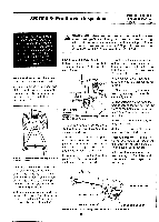
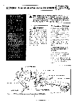
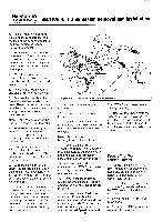
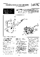
PTO HORSE MODEL TECHNICAL MANUAL SECTION 4: Transmission Removal and Installation Page 4-2 4/90 e. Remove the two mounting bolts and lockwashers that secure the legs of the battery bracket to the transmission cover and remove the bracket. 3. Remove the forward bolt on the right side of the shift lever bracket. Remove the Forward Interlock Wire Harness plug connector with bracket (2) on tillers so equipped. 4. Wrap the engine half of the Forward Interlock Wire Harness assembly (on tillers so equipped) around the engine. 5. Remove the throttle control and cable (3) from the handlebar. 6. Remove the bolt (4) at the forward end of each side of the yoke. These are the bolts that attach the yoke to the engine mount. After you remove these bolts, pull the yoke back. Note: Take care to recover the bushing in each side of the yoke. 7. Remove the bumper/guard attachment. Or, remove the red plugs in the top of the engine mounting bars (5) if a bumper is not attached. 8. Loosen the jam nut on the bolt (6) that retains the engine mounting bar on each side of the PTO power unit. Then remove the bolt from each side. 9. Support the weight of the engine by placing a block under the engine. This is necessary to prevent the engine from falling off when you remove the final engine mounting bar. 10. Lubricate both engine mounting bars. Then, using a punch and taking care to not damage the threads in the top of the engine mounting bars, knock one of the engine mounting bars down and out of the transmission housing and motor mount. 5 8 3 12 14 13 N 11 10 Figure 4-2: Transmission Removal and Installation. 11. Remove the other engine mounting bar. 12. Remove the engine from the tiller. 13. Remove the two final bolts (7) that hold the yoke pivot links to the PTO power unit and remove the yoke. Note: Take care to recover the bushing in each side of the yoke. 14. Remove the bolt (8) or T-handle that holds the handlebar mounting base to the transmission housing cover and remove the base and the attached handlebars. 15. Remove the bolt (9) that holds the Tines/PTO Clutch Lever knob (12) to the lever. Then remove the knob. 16. Remove the locknut that retains the wheel speed lever connecting rod swivel to the eccentric lever (10). 17. Remove the two final bolts from the shift lever bracket (11), one from the top left side and one from the right side. Then remove the bracket along with the attached Wheel Speed Lever and I Tines/PTO Clutch Lever detent shifting plate (15). 18. Remove the wheels from the wheel shaft. See the Owner/Operator Manual for instructions. Or, if the wheel is rusted on the shaft, see "Removing a Rusted Wheel" in Section 7 of this manual. Separating the Transmissions 1. Put the transmission (PTO power unit and tiller attachment assembly) on the floor, a workbench, or other surface that is comfortable for you. 2. Loosen the swing bolts (shown in Figure 4-1) that join the PTO power unit and tiller attachment. 3. Swing the bolts off the tiller attachment. 4. Separate the PTO power unit from the tiller attachment.
-
 1
1 -
2
-
3
-
4
-
5
-
6
-
7
-
8
-
 9
9 -
 10
10 -
 11
11 -
 12
12 -
 13
13 -
 14
14 -
 15
15 -
 16
16 -
 17
17 -
 18
18 -
 19
19 -
20
-
21
-
22
-
23
-
24
-
25
-
26
-
27
-
28
-
29
-
30
-
31
-
32
-
33
-
34
-
35
-
36
-
37
-
38
-
39
 |
 |
