Troy-Bilt Horse Tiller Technical Manual - Page 30
Tiller, Shaft, Assembly
 |
View all Troy-Bilt Horse Tiller manuals
Add to My Manuals
Save this manual to your list of manuals |
Page 30 highlights
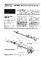
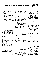
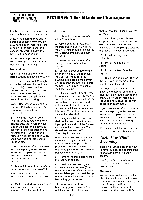
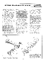
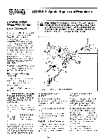
PTO HORSE MODEL TECHNICAL MANUAL Page 6-3 4/90 SECTION 6: Tiller Attachment Transmission tion has not been maintained; discard the bearing and bearing cup. Also, if the bearing or its cup is scored or excessively worn, dirt may have gotten inside the transmission. If the cup is scored or excessively worn, discard the bearing and bearing cup. Inspect for chipped or broken roller bearings, and inspect the bearing cage for damage. Installation Use Figure 6-1 as a reference for part locations in these instructions. 1. Spread a layer of #30 weight oil on the inside of the front bearing cup (14). Make sure the beveled cup is facing the correct way to receive the bearing and insert the bearing cup into the front of the tiller housing. Note: Remember to match the bearings to the bearing cups as you found them before disassembly. 2. Install the (internal) snap ring (15) used to retain the front bearing cup. Make sure the flat side of the snap ring is towards the front of the tiller attachment (towards the PTO power unit). Although not easy to observe, the snap ring has a flat side and a rounded side. If you have some difficulty inserting the snap ring in the groove, insert the ring past the groove. Then use the drive shaft to slide the ring forward and into the groove. 3. Using #30 weight oil, lubricate both bearings on the drive shaft. Note: Follow this procedure to install new bearings on the drive shaft: a. On the welded worm style drive shaft only, place the shoulder washer (17) on the front of the drive shaft. b. Lubricate the new bearings with #30 weight oil. c. Using an arbor press, install the front bearing until it stops at the drive shaft shoulder. Install the rear bearing until it stops against the worm. 4. Insert the tiller drive shaft (11) through the rear of the tiller housing. 5. Spread a layer of #30 weight oil on the inside of the rear bearing cup (12). Make sure the beveled cup is facing the correct way to receive the bearing. Insert the bearing cup into the back of the tiller housing. 6. Place a gasket (9) on the rear bearing cap (7) and gently tap the cap into place. Securely attach the cap with all three screws but do not use a gasket sealer on the screws or install nylon washers at this point. You will next check for play in the drive shaft. 7. Using a mallet, tap the drive shaft to the rear to seat the bearing cup. Push and pull the forward end of the tiller drive shaft. You should feel between .005" and .010" play in the shaft. Remove the rear bearing cap and shim accordingly (start with the thinnest shims). Repeat this procedure until the forward and backward play in the drive shaft is between .005" and .010" 8. Remove the three screws from the rear bearing cap. 9. Install the rear bearing cap and secure it with screws (6) and nylon washers (8). If washers are not available, you can coat the tip of the screws with a layer of nonhardening gasket sealer. 10. Apply a layer of nonhardening gasket sealer to the outside edge of the tiller drive 3d shaft oil seal (13). Then install the oil seal. 11. Install the (external) rear snap ring (2a) that retains the dog clutch to the shaft. Make sure the flat side of the snap ring is towards the rear of the tiller attachment. 12. Install the dog clutch shim (5). 13. Install the dog clutch spring (4). 14. Install the key (3) in the keyway. 15. Slide the dog clutch (1) over the key, with the "ears" on the clutch facing forward. 16. Push the dog clutch in and install the (external) snap ring (2) that retains the dog clutch to the shaft. Make sure the flat side of the snap ring is towards the front of the tiller attachment. If you have some difficulty inserting the snap ring in the groove, insert the ring past the groove. Then let the dog clutch slide forward and it will push the ring forward into the groove. 17. Install the tiller tine shaft. See the instructions in this section. Tiller Tine Shaft Assembly These instructions describe how to remove, inspect, and install the tiller attachment's tine shaft assembly. Use Figure 6-2 as a reference for part locations in these instructions. Removal You will have to disassemble the tiller tine shaft assembly to replace a damaged worm gear, bearing, or shaft. Also, you will have to remove the tiller tine shaft to remove the tiller drive shaft. See
-
 1
1 -
2
-
3
-
4
-
5
-
6
-
7
-
8
-
9
-
10
-
11
-
12
-
13
-
14
-
15
-
16
-
17
-
18
-
19
-
20
-
21
-
22
-
23
-
24
-
 25
25 -
 26
26 -
 27
27 -
 28
28 -
 29
29 -
 30
30 -
 31
31 -
 32
32 -
 33
33 -
 34
34 -
 35
35 -
36
-
37
-
38
-
39
 |
 |
