Troy-Bilt Horse Tiller Technical Manual - Page 13
Transmission, Removal, Installation
 |
View all Troy-Bilt Horse Tiller manuals
Add to My Manuals
Save this manual to your list of manuals |
Page 13 highlights
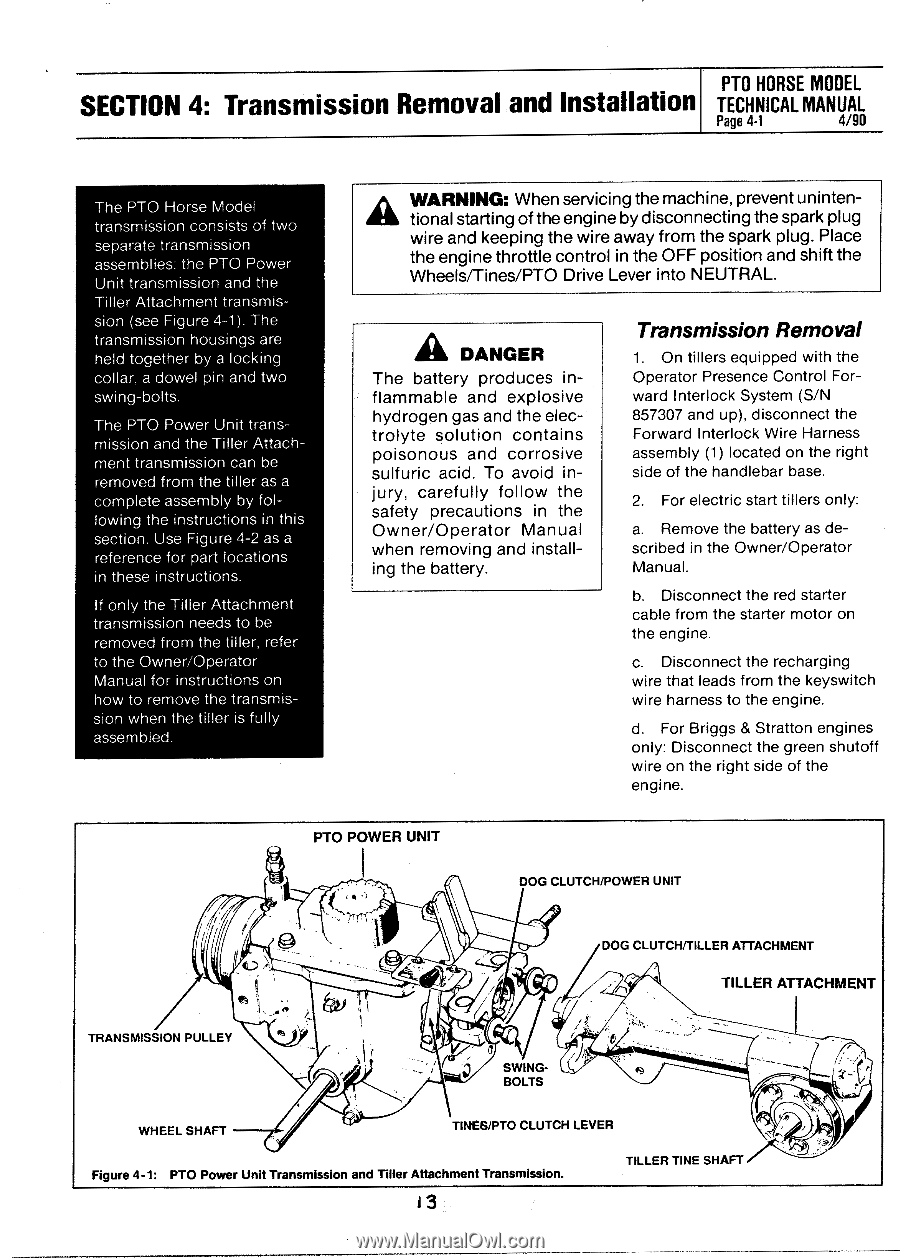
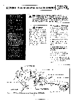
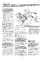
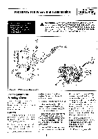
PTO HORSE MODEL SECTION 4: Transmission Removal and Installation TECHNICAL MANUAL Page 4-1 4/90 The PTO Horse Model transmission consists of two separate transmission assemblies: the PTO Power Unit transmission and the Tiller Attachment transmission (see Figure 4-1). The transmission housings are held together by a locking collar, a dowel pin and two swing-bolts. The PTO Power Unit transmission and the Tiller Attachment transmission can be removed from the tiller as a complete assembly by following the instructions in this section. Use Figure 4-2 as a reference for part locations in these instructions. If only the Tiller Attachment transmission needs to be removed from the tiller, refer to the Owner/Operator Manual for instructions on how to remove the transmission when the tiller is fully assembled. A WARNING: When servicing the machine, prevent unintentional starting of the engine by disconnecting the spark plug wire and keeping the wire away from the spark plug. Place the engine throttle control in the OFF position and shift the Wheels/Tines/PTO Drive Lever into NEUTRAL. A DANGER The battery produces inflammable and explosive hydrogen gas and the electrolyte solution contains poisonous and corrosive sulfuric acid. To avoid injury, carefully follow the safety precautions in the Owner/Operator Manual when removing and installing the battery. Transmission Removal 1. On tillers equipped with the Operator Presence Control Forward Interlock System (S/N 857307 and up), disconnect the Forward Interlock Wire Harness assembly (1) located on the right side of the handlebar base. 2. For electric start tillers only: a. Remove the battery as described in the Owner/Operator Manual. b. Disconnect the red starter cable from the starter motor on the engine. c. Disconnect the recharging wire that leads from the keyswitch wire harness to the engine. d. For Briggs & Stratton engines only: Disconnect the green shutoff wire on the right side of the engine. PTO POWER UNIT ( • •~ DOG CLUTCH/POWER UNIT 4I TRANSMISSION PULLEY DOG CLUTCH/TILLER ATTACHMENT TILLER ATTACHMENT SWINGBOLTS WHEEL SHAFT TINES/PTO CLUTCH LEVER ,07 Figure 4-1: PTO Power Unit Transmission and Tiller Attachment Transmission. 3 TILLER TINE SHAFT
-
 1
1 -
2
-
3
-
4
-
5
-
6
-
7
-
 8
8 -
 9
9 -
 10
10 -
 11
11 -
 12
12 -
 13
13 -
 14
14 -
 15
15 -
 16
16 -
 17
17 -
 18
18 -
19
-
20
-
21
-
22
-
23
-
24
-
25
-
26
-
27
-
28
-
29
-
30
-
31
-
32
-
33
-
34
-
35
-
36
-
37
-
38
-
39
 |
 |