2014 Ford F150 SuperCrew Cab Owner Manual Printing 1 - Page 295
2014 Ford F150 SuperCrew Cab Manual

Page 295 highlights
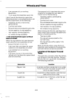
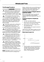
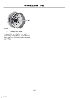
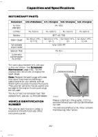
Wheels and Tires 2. Slide the wheel partially under the vehicle and install the retainer through the wheel center. Pull on the cable to align the components at the end of the cable. 3. Turn the jack handle clockwise until the tire is raised to its stowed position underneath the vehicle. The effort to turn the jack handle increases significantly and the spare tire carrier ratchets or slips when the tire is raised to the maximum tightness. Tighten to the best of your ability, to the point where the ratchet or slip occurs, if possible. The spare tire carrier will not allow you to overtighten. If the spare tire carrier ratchets or slips with little effort, take the vehicle to your authorized dealer for assistance at your earliest convenience. 4. Check that the tire lies flat against the frame and is properly tightened. Try to push or pull, then turn the tire to be sure it will not move. Loosen and retighten, if necessary. Failure to properly stow the spare tire may result in failure of the winch cable and loss of the tire. 5. Repeat this tightness check procedure when servicing the spare tire pressure (every six months, as per your scheduled maintenance information), or at any time that the spare tire is disturbed through service of other components. 6. If removed, install the spare tire lock into the bumper drive tube with the spare tire lock key and jack handle. TECHNICAL SPECIFICATIONS Wheel Lug Nut Torque Specifications WARNING When a wheel is installed, always remove any corrosion, dirt or foreign materials present on the mounting surfaces of the wheel or the surface of the wheel hub, brake drum or brake disc that contacts the wheel. Make sure that any fasteners that attach the rotor to the hub are secured so they do not interfere with the mounting surfaces of the wheel. Installing wheels without correct metal-to-metal contact at the wheel mounting surfaces can cause the wheel nuts to loosen and the wheel to come off while your vehicle is in motion, resulting in loss of control. Bolt size lbf.ft (Nm) M14 x 2.0 * 148 lbf.ft (200 Nm) Torque specifications are for nut and bolt threads free of dirt and rust. Use only Ford recommended replacement fasteners. 293 F150 (TF6)
-
 1
1 -
2
-
3
-
4
-
5
-
6
-
7
-
8
-
9
-
10
-
11
-
12
-
13
-
14
-
15
-
16
-
17
-
18
-
19
-
20
-
21
-
22
-
23
-
24
-
25
-
26
-
27
-
28
-
29
-
30
-
31
-
32
-
33
-
34
-
35
-
36
-
37
-
38
-
39
-
40
-
41
-
42
-
43
-
44
-
45
-
46
-
47
-
48
-
49
-
50
-
51
-
52
-
53
-
54
-
55
-
56
-
57
-
58
-
59
-
60
-
61
-
62
-
63
-
64
-
65
-
66
-
67
-
68
-
69
-
70
-
71
-
72
-
73
-
74
-
75
-
76
-
77
-
78
-
79
-
80
-
81
-
82
-
83
-
84
-
85
-
86
-
87
-
88
-
89
-
90
-
91
-
92
-
93
-
94
-
95
-
96
-
97
-
98
-
99
-
100
-
101
-
102
-
103
-
104
-
105
-
106
-
107
-
108
-
109
-
110
-
111
-
112
-
113
-
114
-
115
-
116
-
117
-
118
-
119
-
120
-
121
-
122
-
123
-
124
-
125
-
126
-
127
-
128
-
129
-
130
-
131
-
132
-
133
-
134
-
135
-
136
-
137
-
138
-
139
-
140
-
141
-
142
-
143
-
144
-
145
-
146
-
147
-
148
-
149
-
150
-
151
-
152
-
153
-
154
-
155
-
156
-
157
-
158
-
159
-
160
-
161
-
162
-
163
-
164
-
165
-
166
-
167
-
168
-
169
-
170
-
171
-
172
-
173
-
174
-
175
-
176
-
177
-
178
-
179
-
180
-
181
-
182
-
183
-
184
-
185
-
186
-
187
-
188
-
189
-
190
-
191
-
192
-
193
-
194
-
195
-
196
-
197
-
198
-
199
-
200
-
201
-
202
-
203
-
204
-
205
-
206
-
207
-
208
-
209
-
210
-
211
-
212
-
213
-
214
-
215
-
216
-
217
-
218
-
219
-
220
-
221
-
222
-
223
-
224
-
225
-
226
-
227
-
228
-
229
-
230
-
231
-
232
-
233
-
234
-
235
-
236
-
237
-
238
-
239
-
240
-
241
-
242
-
243
-
244
-
245
-
246
-
247
-
248
-
249
-
250
-
251
-
252
-
253
-
254
-
255
-
256
-
257
-
258
-
259
-
260
-
261
-
262
-
263
-
264
-
265
-
266
-
267
-
268
-
269
-
270
-
271
-
272
-
273
-
274
-
275
-
276
-
277
-
278
-
279
-
280
-
281
-
282
-
283
-
284
-
285
-
286
-
287
-
288
-
289
-
 290
290 -
 291
291 -
 292
292 -
 293
293 -
 294
294 -
 295
295 -
 296
296 -
 297
297 -
 298
298 -
 299
299 -
 300
300 -
301
-
302
-
303
-
304
-
305
-
306
-
307
-
308
-
309
-
310
-
311
-
312
-
313
-
314
-
315
-
316
-
317
-
318
-
319
-
320
-
321
-
322
-
323
-
324
-
325
-
326
-
327
-
328
-
329
-
330
-
331
-
332
-
333
-
334
-
335
-
336
-
337
-
338
-
339
-
340
-
341
-
342
-
343
-
344
-
345
-
346
-
347
-
348
-
349
-
350
-
351
-
352
-
353
-
354
-
355
-
356
-
357
-
358
-
359
-
360
-
361
-
362
-
363
-
364
-
365
-
366
-
367
-
368
-
369
-
370
-
371
-
372
-
373
-
374
-
375
-
376
-
377
-
378
-
379
-
380
-
381
-
382
-
383
-
384
-
385
-
386
-
387
-
388
-
389
-
390
-
391
-
392
-
393
-
394
-
395
-
396
-
397
-
398
-
399
-
400
-
401
-
402
-
403
-
404
-
405
-
406
-
407
-
408
-
409
-
410
-
411
-
412
-
413
-
414
-
415
-
416
-
417
-
418
-
419
-
420
-
421
-
422
-
423
-
424
-
425
-
426
-
427
-
428
-
429
-
430
-
431
-
432
-
433
-
434
-
435
-
436
-
437
-
438
-
439
-
440
-
441
-
442
-
443
-
444
-
445
-
446
-
447
-
448
-
449
-
450
-
451
-
452
-
453
-
454
-
455
-
456
-
457
-
458
-
459
-
460
-
461
-
462
-
463
-
464
-
465
-
466
-
467
-
468
-
469
 |
 |