Cisco RV042 Administration Guide - Page 176
Example: Sites with Static WAN IP Addresses
 |
UPC - 745883560530
View all Cisco RV042 manuals
Add to My Manuals
Save this manual to your list of manuals |
Page 176 highlights
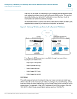
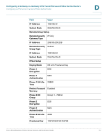
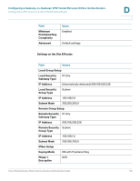
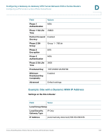
Configuring a Gateway-to-Gateway VPN Tunnel Between RV0xx Series Routers Configuring a VPN Tunnel on a Cisco RV0xx Series Router D - If the remote gateway (Site B) has a dynamic IP address and a Dynamic DNS hostname: Select Dynamic IP + Domain Name (FQDN) Authentication. Enter the registered Domain Name of the Site B router, such as MyBusiness.DynDNS.org. • Remote Security Group Type-Select Subnet. Enter the LAN IP Address and Subnet Mask of the Site B router. STEP 6 In the IPSec Setup section, keep the default settings (recommended) or enter other settings if desired. Ensure that you configure the Site B router with the same settings. STEP 7 In the Preshared Key field, enter a string for this key, for example, 13572468. Ensure that you configure the other router with the same preshared key. STEP 8 If you need more detailed settings, click Advanced. Otherwise, click Save. Note: Advanced settings can be used to enable features such as dead peer detection, NAT traversal, split DNS, and NetBIOS broadcast messages. STEP 9 At the remote site (Site B), set up the router with the corresponding settings (where Site B is the "local gateway" and Site A is the "remote gateway:). STEP 10 Use the VPN > Summary page to verify that the tunnel is active. STEP 11 Verify that a computer at Site A can ping a computer at Site B, and vice versa. (Refer to Windows Help for more information). If the ping test is successful, then the VPN tunnel is configured correctly. STEP 12 Repeat this procedure to configure additional VPN tunnel. Example: Sites with Static WAN IP Addresses Settings on the Site A Router: Field Value Local Group Setup Local Security Gateway Type IP Only IP Address (Automatically detected) 203.165.200.226 Local Security Group Type Subnet Cisco Small Business RV0xx Series Routers Administration Guide 176
-
 1
1 -
2
-
3
-
4
-
5
-
6
-
7
-
8
-
9
-
10
-
11
-
12
-
13
-
14
-
15
-
16
-
17
-
18
-
19
-
20
-
21
-
22
-
23
-
24
-
25
-
26
-
27
-
28
-
29
-
30
-
31
-
32
-
33
-
34
-
35
-
36
-
37
-
38
-
39
-
40
-
41
-
42
-
43
-
44
-
45
-
46
-
47
-
48
-
49
-
50
-
51
-
52
-
53
-
54
-
55
-
56
-
57
-
58
-
59
-
60
-
61
-
62
-
63
-
64
-
65
-
66
-
67
-
68
-
69
-
70
-
71
-
72
-
73
-
74
-
75
-
76
-
77
-
78
-
79
-
80
-
81
-
82
-
83
-
84
-
85
-
86
-
87
-
88
-
89
-
90
-
91
-
92
-
93
-
94
-
95
-
96
-
97
-
98
-
99
-
100
-
101
-
102
-
103
-
104
-
105
-
106
-
107
-
108
-
109
-
110
-
111
-
112
-
113
-
114
-
115
-
116
-
117
-
118
-
119
-
120
-
121
-
122
-
123
-
124
-
125
-
126
-
127
-
128
-
129
-
130
-
131
-
132
-
133
-
134
-
135
-
136
-
137
-
138
-
139
-
140
-
141
-
142
-
143
-
144
-
145
-
146
-
147
-
148
-
149
-
150
-
151
-
152
-
153
-
154
-
155
-
156
-
157
-
158
-
159
-
160
-
161
-
162
-
163
-
164
-
165
-
166
-
167
-
168
-
169
-
170
-
 171
171 -
 172
172 -
 173
173 -
 174
174 -
 175
175 -
 176
176 -
 177
177 -
 178
178 -
 179
179 -
 180
180 -
 181
181 -
182
-
183
-
184
-
185
-
186
-
187
-
188
-
189
-
190
-
191
-
192
-
193
-
194
-
195
-
196
-
197
-
198
-
199
 |
 |
