Cisco WS-C2960S-24TS-S Hardware Installation Guide - Page 28
Dual-Purpose Port LEDs, Port Mode, LED Color, Meaning
 |
View all Cisco WS-C2960S-24TS-S manuals
Add to My Manuals
Save this manual to your list of manuals |
Page 28 highlights
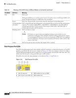
Front Panel Description Chapter 1 Product Overview Table 1-6 Port Mode PoE Meaning of Port LED Colors in Different Modes on the Switch (continued) LED Color Off Meaning PoE is off. If the powered device is receiving power from an AC power source, the PoE port LED is off even if the powered device is connected to the switch port. Green PoE is on. The port LED is green only when the switch port is providing power. Alternating green PoE is denied because providing power to the powered device will exceed the switch power and amber capacity. The Catalyst 2960-24PC-L, 2960 48PST-L, 2960-48PST-S, and 2960-24PC-S switches provide up to 370 W of power. The Catalyst 2960-24LT-L and 2960-24LC-S switches provide up to 124 W of power. Blinking amber PoE is off due to a fault. Amber Caution PoE faults are caused when noncompliant cabling or powered devices are connected to a PoE port. Only standard-compliant cabling can be used to connect Cisco prestandard IP Phones or wireless access points or IEEE 802.3af-compliant devices to PoE ports. You must remove from the network the cable or device that causes a PoE fault. PoE for the port has been disabled. By default, PoE is enabled. Dual-Purpose Port LEDs The LEDs on a dual-purpose port show whether an RJ-45 connector is connected to the port, or if an SFP module is installed in the slot. See the example in Figure 1-24. You can configure each port as either a 10/100/1000 port through the RJ-45 connector or as an SFP module, but not both at the same time. The LEDs show how the port is being used (Ethernet or SFP module). The LED colors have the same meanings as described in Table 1-4 and Table 1-6. Figure 1-24 Dual-Purpose Port LEDs 1 234 1 1 RJ-45 connector 3 SFP module port in-use LED 2 RJ-45 port in-use LED 4 SFP module slot 1-18 Catalyst 2960 Switch Hardware Installation Guide OL-7075-09
-
 1
1 -
2
-
3
-
4
-
5
-
6
-
7
-
8
-
9
-
10
-
11
-
12
-
13
-
14
-
15
-
16
-
17
-
18
-
19
-
20
-
21
-
22
-
 23
23 -
 24
24 -
 25
25 -
 26
26 -
 27
27 -
 28
28 -
 29
29 -
 30
30 -
 31
31 -
 32
32 -
 33
33 -
34
-
35
-
36
-
37
-
38
-
39
-
40
-
41
-
42
-
43
-
44
-
45
-
46
-
47
-
48
-
49
-
50
-
51
-
52
-
53
-
54
-
55
-
56
-
57
-
58
-
59
-
60
-
61
-
62
-
63
-
64
-
65
-
66
-
67
-
68
-
69
-
70
-
71
-
72
-
73
-
74
-
75
-
76
-
77
-
78
-
79
-
80
-
81
-
82
-
83
-
84
-
85
-
86
-
87
-
88
-
89
-
90
-
91
-
92
-
93
-
94
-
95
-
96
-
97
-
98
-
99
-
100
-
101
-
102
-
103
-
104
-
105
-
106
-
107
-
108
 |
 |
