Cisco WS-C2960S-24TS-S Hardware Installation Guide - Page 51
Connecting to 1000BASE-T SFP Modules
 |
View all Cisco WS-C2960S-24TS-S manuals
Add to My Manuals
Save this manual to your list of manuals |
Page 51 highlights
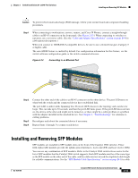
Chapter 2 Switch Installation (24- and 48-Port Switches) Connecting to SFP Modules Step 1 Remove the rubber plugs from the module port and fiber-optic cable, and store them for future use. Step 2 Insert one end of the fiber-optic cable into the SFP module port (see Figure 2-17). Figure 2-17 Connecting to a Fiber-Optic SFP Module Port 204624 1 1 LC connector Step 3 Step 4 Step 5 Insert the other cable end into a fiber-optic receptacle on a target device. Observe the port status LED. The LED turns green when the switch and the target device have an established link. The LED turns amber while the STP discovers the network topology and searches for loops. This process takes about 30 seconds, and then the port LED turns green. If the LED is off, the target device might not be turned on, there might be a cable problem, or there might be problem with the adapter installed in the target device. See Chapter 4, "Troubleshooting," for solutions to cabling problems. If necessary, reconfigure and restart the switch or target device. Connecting to 1000BASE-T SFP Modules Caution To prevent ESD damage, follow your normal board and component handling procedures. Step 1 Insert one end of the cable into the SFP module port (see Figure 2-18). When connecting to servers, workstations, and routers, insert a four twisted-pair, straight-through cable in the RJ-45 connector. When connecting to switches or repeaters, insert a four twisted-pair, crossover cable. Note When connecting to a 1000BASE-T device, be sure to use a four twisted-pair, Category 5 or higher cable. OL-7075-09 Catalyst 2960 Switch Hardware Installation Guide 2-19
-
 1
1 -
2
-
3
-
4
-
5
-
6
-
7
-
8
-
9
-
10
-
11
-
12
-
13
-
14
-
15
-
16
-
17
-
18
-
19
-
20
-
21
-
22
-
23
-
24
-
25
-
26
-
27
-
28
-
29
-
30
-
31
-
32
-
33
-
34
-
35
-
36
-
37
-
38
-
39
-
40
-
41
-
42
-
43
-
44
-
45
-
 46
46 -
 47
47 -
 48
48 -
 49
49 -
 50
50 -
 51
51 -
 52
52 -
 53
53 -
 54
54 -
 55
55 -
 56
56 -
57
-
58
-
59
-
60
-
61
-
62
-
63
-
64
-
65
-
66
-
67
-
68
-
69
-
70
-
71
-
72
-
73
-
74
-
75
-
76
-
77
-
78
-
79
-
80
-
81
-
82
-
83
-
84
-
85
-
86
-
87
-
88
-
89
-
90
-
91
-
92
-
93
-
94
-
95
-
96
-
97
-
98
-
99
-
100
-
101
-
102
-
103
-
104
-
105
-
106
-
107
-
108
 |
 |
