Cisco WS-C2960S-24TS-S Hardware Installation Guide - Page 47
Installing and Removing SFP Modules
 |
View all Cisco WS-C2960S-24TS-S manuals
Add to My Manuals
Save this manual to your list of manuals |
Page 47 highlights
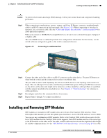
Chapter 2 Switch Installation (24- and 48-Port Switches) Installing and Removing SFP Modules Caution To prevent electrostatic-discharge (ESD) damage, follow your normal board and component handling procedures. Step 1 When connecting to workstations, servers, routers, and Cisco IP Phones, connect a straight-through cable to an RJ-45 connector on the front panel. (See Figure 2-13.) When connecting to switches or repeaters, use a crossover cable. (See the "Cable and Adapter Specifications" section on page B-4 for cable-pinout descriptions.) When you connect to 1000BASE-T-compatible devices, be sure to use a twisted four-pair, Category 5 or higher cable. The auto-MDIX feature is enabled by default. For configuration information for this feature, see the switch software configuration guide or the switch command reference. Figure 2-13 Connecting to an Ethernet Port 11XX SYST RPS STAT DUPLX 111X SPEED 2X MODE 12X 204623 Step 2 Step 3 Step 4 Connect the other end of the cable to an RJ-45 connector on the other device. The port LED turns on when both the switch and the connected device have established link. The port LED is amber while Spanning Tree Protocol (STP) discovers the topology and searches for loops. This can take up to 30 seconds, and then the port LED turns green. If the port LED does not turn on, the device at the other end might not be turned on, or there might be a cable problem or a problem with the adapter installed in the attached device. See Chapter 4, "Troubleshooting," for solutions to cabling problems. Reconfigure and reboot the connected device if necessary. Repeat Steps 1 through 3 to connect each device. Installing and Removing SFP Modules SFP modules are installed in SFP module slots on the front of the Catalyst 2960 switches. These field-replaceable modules provide the uplink optical interfaces, laser send (TX) and laser receive (RX). You can use any combination of SFP modules. Refer to the Catalyst 2960 switch release notes for the list of SFP modules that the Catalyst 2960 switch supports. Each SFP module must be of the same type as the SFP module on the other end of the cable, and the cable must not exceed the stipulated cable length for reliable communications. See the "SFP Module Cable Specifications" section on page B-4 for cable OL-7075-09 Catalyst 2960 Switch Hardware Installation Guide 2-15
-
 1
1 -
2
-
3
-
4
-
5
-
6
-
7
-
8
-
9
-
10
-
11
-
12
-
13
-
14
-
15
-
16
-
17
-
18
-
19
-
20
-
21
-
22
-
23
-
24
-
25
-
26
-
27
-
28
-
29
-
30
-
31
-
32
-
33
-
34
-
35
-
36
-
37
-
38
-
39
-
40
-
41
-
 42
42 -
 43
43 -
 44
44 -
 45
45 -
 46
46 -
 47
47 -
 48
48 -
 49
49 -
 50
50 -
 51
51 -
 52
52 -
53
-
54
-
55
-
56
-
57
-
58
-
59
-
60
-
61
-
62
-
63
-
64
-
65
-
66
-
67
-
68
-
69
-
70
-
71
-
72
-
73
-
74
-
75
-
76
-
77
-
78
-
79
-
80
-
81
-
82
-
83
-
84
-
85
-
86
-
87
-
88
-
89
-
90
-
91
-
92
-
93
-
94
-
95
-
96
-
97
-
98
-
99
-
100
-
101
-
102
-
103
-
104
-
105
-
106
-
107
-
108
 |
 |
