Cisco WS-C2960S-24TS-S Hardware Installation Guide - Page 70
Mounting the Switch in a 19-Inch Rack, Wall-Mounting (with Rack-Mount Brackets)
 |
View all Cisco WS-C2960S-24TS-S manuals
Add to My Manuals
Save this manual to your list of manuals |
Page 70 highlights
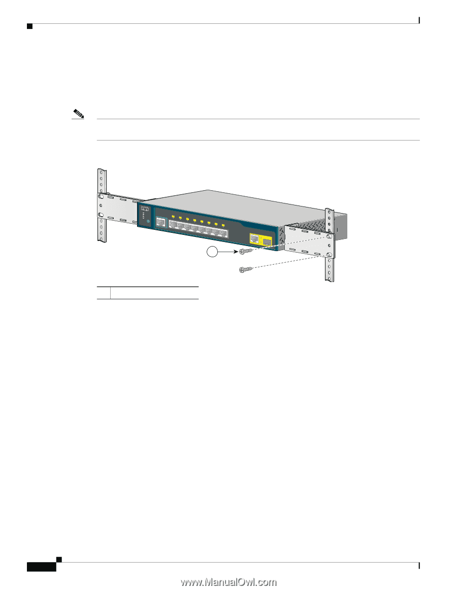
Installing the Switch Chapter 3 Switch Installation (8-Port Switches) Mounting the Switch in a 19-Inch Rack After the brackets are attached to the switch, insert the switch into the 19-inch rack, and align the bracket in the rack. Use either the 10-32 pan-head screws or the 12-24 pan-slotted screws to secure the switch in the rack, as shown in Figure 3-9. Note We strongly recommend that you allow at least 1.75 inches (4 cm) of clearance above each switch in the rack. Figure 3-9 Mounting the Switch in a 19-Inch Rack SYST STAT DPLX SPD MODE CONSOLE 1x 2x 3x 4x 5x 6x 7x 8x 1 Catalyst 2960 Series 1 204638 1 Phillips machine screws After the switch is mounted in the rack, do these tasks to complete the installation: 1. Power on the switch. See the "Verifying Switch Operation" section on page 3-5. 2. Connect to a 10/100 or 10/100/1000 port, and run Express Setup. See the switch getting started guide for instructions. 3. Connect to the front-panel ports. See the "Connecting to the 10/100 and 10/100/1000 Ports" section on page 2-14, the "Connecting to SFP Modules" section on page 2-18, and the "Connecting to a Dual-Purpose Port" section on page 2-20 to complete the installation. For configuration instructions about using the CLI setup program, go to Appendix C, "Configuring the Switch with the CLI-Based Setup Program." Wall-Mounting (with Rack-Mount Brackets) To install the Catalyst 2960 8-port switches in a 19-inch rack requires an optional bracket kit that is not included with the switch. You can order a kit containing the 19-inch rack-mounting brackets and hardware from Cisco. The kit part number is RCKMNT-19-CMPCT=. This section is specific to the Catalyst 2960 8-port switches. For information applicable to the other Catalyst 2960 switches, see Chapter 2, "Switch Installation (24- and 48-Port Switches)." 3-16 Catalyst 2960 Switch Hardware Installation Guide OL-7075-09
-
 1
1 -
2
-
3
-
4
-
5
-
6
-
7
-
8
-
9
-
10
-
11
-
12
-
13
-
14
-
15
-
16
-
17
-
18
-
19
-
20
-
21
-
22
-
23
-
24
-
25
-
26
-
27
-
28
-
29
-
30
-
31
-
32
-
33
-
34
-
35
-
36
-
37
-
38
-
39
-
40
-
41
-
42
-
43
-
44
-
45
-
46
-
47
-
48
-
49
-
50
-
51
-
52
-
53
-
54
-
55
-
56
-
57
-
58
-
59
-
60
-
61
-
62
-
63
-
64
-
 65
65 -
 66
66 -
 67
67 -
 68
68 -
 69
69 -
 70
70 -
 71
71 -
 72
72 -
 73
73 -
 74
74 -
 75
75 -
76
-
77
-
78
-
79
-
80
-
81
-
82
-
83
-
84
-
85
-
86
-
87
-
88
-
89
-
90
-
91
-
92
-
93
-
94
-
95
-
96
-
97
-
98
-
99
-
100
-
101
-
102
-
103
-
104
-
105
-
106
-
107
-
108
 |
 |