Cisco WS-C2960S-24TS-S Hardware Installation Guide - Page 44
Attaching the Brackets to the Switch for Wall-Mounting, Attaching the RPS Connector Cover,
 |
View all Cisco WS-C2960S-24TS-S manuals
Add to My Manuals
Save this manual to your list of manuals |
Page 44 highlights
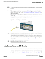
Installing the Switch Chapter 2 Switch Installation (24- and 48-Port Switches) Attaching the Brackets to the Switch for Wall-Mounting Figure 2-10 shows how to attach a 19-inch bracket to one side of the switch. Follow the same steps to attach the second bracket to the opposite side. Figure 2-10 Attaching the 19-inch Brackets for Wall-Mounting 1X 11X 204620 1 1 Phillips truss-head screws Attaching the RPS Connector Cover If your switch has an RPS connector and you are not using an RPS with your switch, use the two Phillips pan-head screws to attach the RPS connector cover to the back of the switch, as shown in Figure 2-11. Note The Catalyst 2960 8-port switches and the Catalyst 2960-24-S, 2960-24TC-S, 2960-48TT-S, and 2960-48TC-S switches do not have an RPS connector. Warning If an RPS is not connected to the switch, install an RPS connector cover on the back of the switch. Statement 265 Figure 2-11 Attaching the RPS Connector Cover on the Catalyst 2960 Switch 137082 CONSOLE 1 2 3 1 Phillips pan-head screws 3 RPS connector 2 RPS connector cover 2-12 Catalyst 2960 Switch Hardware Installation Guide OL-7075-09
-
 1
1 -
2
-
3
-
4
-
5
-
6
-
7
-
8
-
9
-
10
-
11
-
12
-
13
-
14
-
15
-
16
-
17
-
18
-
19
-
20
-
21
-
22
-
23
-
24
-
25
-
26
-
27
-
28
-
29
-
30
-
31
-
32
-
33
-
34
-
35
-
36
-
37
-
38
-
 39
39 -
 40
40 -
 41
41 -
 42
42 -
 43
43 -
 44
44 -
 45
45 -
 46
46 -
 47
47 -
 48
48 -
 49
49 -
50
-
51
-
52
-
53
-
54
-
55
-
56
-
57
-
58
-
59
-
60
-
61
-
62
-
63
-
64
-
65
-
66
-
67
-
68
-
69
-
70
-
71
-
72
-
73
-
74
-
75
-
76
-
77
-
78
-
79
-
80
-
81
-
82
-
83
-
84
-
85
-
86
-
87
-
88
-
89
-
90
-
91
-
92
-
93
-
94
-
95
-
96
-
97
-
98
-
99
-
100
-
101
-
102
-
103
-
104
-
105
-
106
-
107
-
108
 |
 |
