D-Link DES-3226SM Product Manual - Page 19
LED Indicators, Stacking Module LED Indicators
 |
UPC - 790069247118
View all D-Link DES-3226SM manuals
Add to My Manuals
Save this manual to your list of manuals |
Page 19 highlights
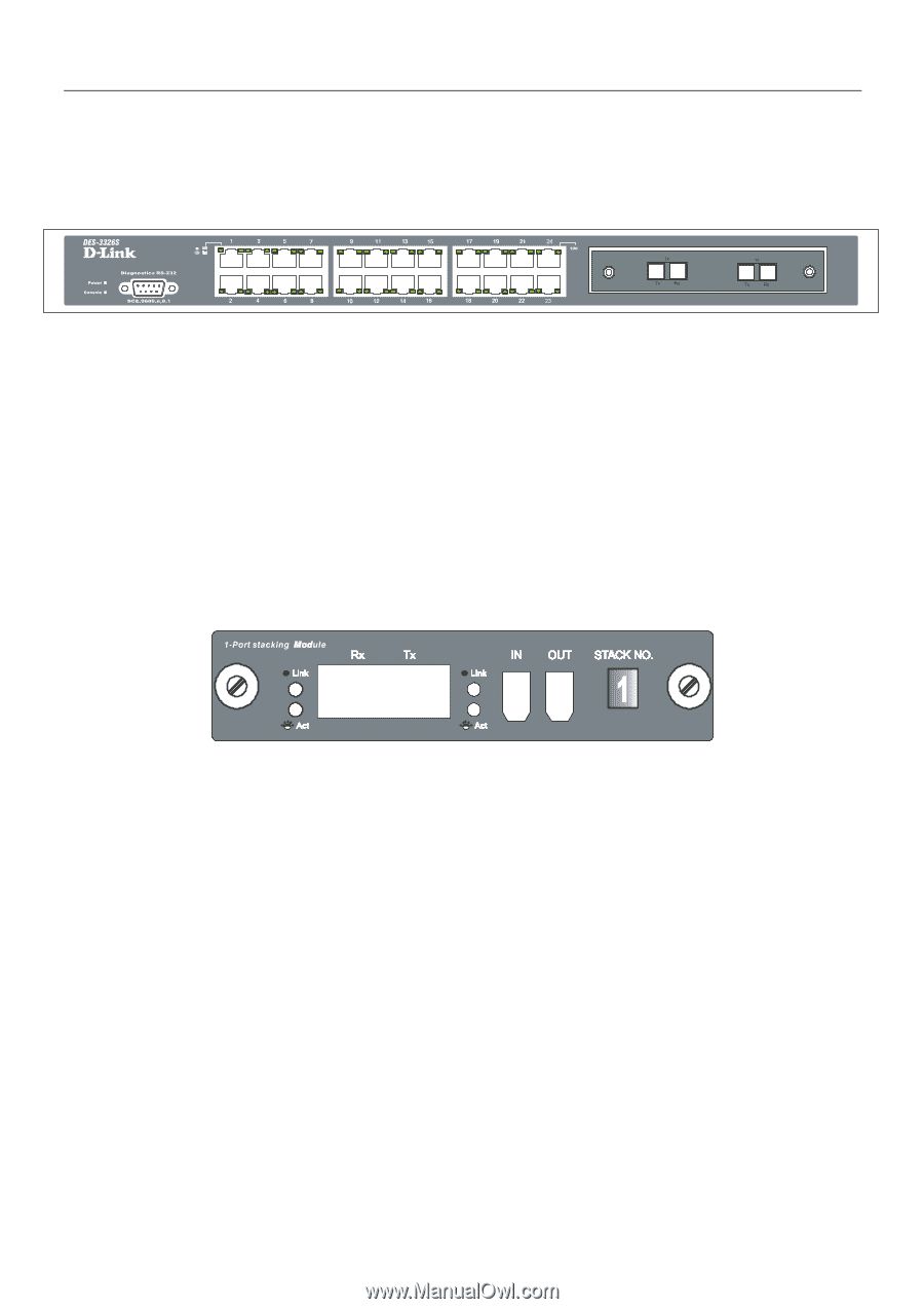
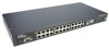
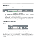
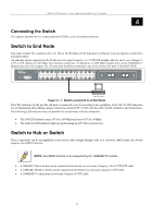
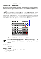
DES-3226S Layer 2 Fast Ethernet Switch User's Guide LED Indicators The LED indicators of the Switch include Power, Console, and Link/Act. The following shows the LED indicators for the Switch along with an explanation of each indicator. Figure 3 - 12. The LED Indicators • Power This indicator on the front panel should be lit during the Power-On Self Test (POST). It will light green approximately 2 seconds after the Switch is powered on to indicate the ready state of the device. • Console This indicator is lit green when the Switch is being managed via out-of-band/local console management through the RS-232 console port using a straight-through serial cable. • Act/Link/Speed These indicators are located to the left and right of each port. The right side indicator will light when the port has a link of 100 Mbps; the Link indicator will not light for 10 Mbps links. The LEDs blink whenever there is reception or transmission (i.e. Activity--Act) of data occurring at a port. Stacking Module LED Indicators The Switch's current order in the Switch stack is also displayed on the Stacking Module's front panel − under the STACK NO. heading: Figure 3 - 13. Stacking Module LED Indicators The Link and Act LEDs have the same function as the corresponding LEDs for the Switch's Ethernet ports. The Link LED lights to confirm a valid link, while the ACT LED blinks to indicate activity on the link. The Stack No. seven-segment LED displays the unit number assigned to the Switch. The numeral 1 in the display indicates that the stacking module is in the process of determining the stack status and has not yet resolved the Switch's unit number. If the master Switch fails, a new master Switch should be configured for the stack until the failure can be fixed. Any time the composition of a stacked Switch group changes, all Switches in the stack will reboot automatically and the master-slave relationship and stack number will be renegotiated. A link failure will require reconnecting the stacking ports to work around the failed link. 16
-
 1
1 -
2
-
3
-
4
-
5
-
6
-
7
-
8
-
9
-
10
-
11
-
12
-
13
-
 14
14 -
 15
15 -
 16
16 -
 17
17 -
 18
18 -
 19
19 -
 20
20 -
 21
21 -
 22
22 -
 23
23 -
 24
24 -
25
-
26
-
27
-
28
-
29
-
30
-
31
-
32
-
33
-
34
-
35
-
36
-
37
-
38
-
39
-
40
-
41
-
42
-
43
-
44
-
45
-
46
-
47
-
48
-
49
-
50
-
51
-
52
-
53
-
54
-
55
-
56
-
57
-
58
-
59
-
60
-
61
-
62
-
63
-
64
-
65
-
66
-
67
-
68
-
69
-
70
-
71
-
72
-
73
-
74
-
75
-
76
-
77
-
78
-
79
-
80
-
81
-
82
-
83
-
84
-
85
-
86
-
87
-
88
-
89
-
90
-
91
-
92
-
93
-
94
-
95
-
96
-
97
-
98
-
99
-
100
-
101
-
102
-
103
-
104
-
105
-
106
-
107
-
108
-
109
-
110
-
111
-
112
-
113
-
114
-
115
-
116
-
117
-
118
-
119
-
120
-
121
-
122
-
123
-
124
 |
 |