D-Link DES-3226SM Product Manual - Page 25
Convert a Standalone Switch to a Stacked Switch, Add a Switch to a Stack
 |
UPC - 790069247118
View all D-Link DES-3226SM manuals
Add to My Manuals
Save this manual to your list of manuals |
Page 25 highlights
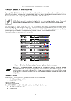
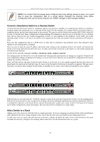
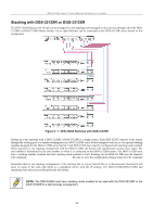
DES-3226S Layer 2 Fast Ethernet Switch User's Guide NOTE: For a Switch that has already been configured with many settings already in place, it is a good idea to save the configuration files to a server before changing the stacking mode status. Configuration files can be saved using the CLI, SNMP manager or web manager interface. Convert a Standalone Switch to a Stacked Switch A Switch that has previously acted in a standalone capacity may become a member of a stacked group simply by installing a stacking module and connecting it to a connected Switch stack. For this example, let's assume Switch A has been setup as a standalone device and has been functioning on the network. We want to join this Switch with another DES-3226S, Switch B, to form a 2-Switch stack. Many configuration settings including IP settings have already been set on Switch A so we will keep these and use them for the new stacked arrangement. Switch A is also uplinked to the backbone via the GBIC port in the stacking module. Switch A will stay in its position in the uppermost slot in the rack and all network connections will remain in place. First, save the configuration files to a TFTP server so they may be reloaded if any problems occur. This should be done whether or not stacking mode is changed. Since we want to keep the same IP address and all the other setting on the standalone Switch, this Switch will become the master of the stack and Switch B will be the slave. To make sure Switch A functions as the master we will enable stacking and override the auto function. Use the CLI to enter the command: config stacking mode enable master The stacking mode for Switch B is set to the default auto-stacking mode and therefore no changes are required. Switch B will lose configuration settings including its IP settings, so if you want to save these be sure to upload the configuration files before making the stacking connection. Power off both devices and place Switch B under Switch A in the rack. It is not actually required that the slave device be placed under the master in the stack but it may be easier so that the master Switch may be instantly recognized. This may prove especially convenient where multiple Switch stacks are installed so it is always clear which unit should be used to uplink. Both Switches are now powered off. Switch B is placed securely in the rack and connected to Switch A via the stacking ports. Both devices are powered on; they recognize the stacking connection and begin negotiating the stacking relationship. Switch A is configured to function as the master device. Switch B automatically assume slave status. Switch A will keep its IP settings and its other configurations remain unchanged. The stack may now be configured as a single entity. Add a Switch to a Stack Adding a new slave device to a Switch stack is a simple procedure. If you are swapping an existing Switch, label each Ethernet cable attached to the device being swapped so they can be placed in the same port number in the replacement device. To add a new slave to a stack, place the new unit in the next available slot below the stack. Power off all Switches in the stack and make the necessary changes to the stacking cable connections. Use the illustrations below as a guide. 22
-
 1
1 -
2
-
3
-
4
-
5
-
6
-
7
-
8
-
9
-
10
-
11
-
12
-
13
-
14
-
15
-
16
-
17
-
18
-
19
-
 20
20 -
 21
21 -
 22
22 -
 23
23 -
 24
24 -
 25
25 -
 26
26 -
 27
27 -
 28
28 -
 29
29 -
 30
30 -
31
-
32
-
33
-
34
-
35
-
36
-
37
-
38
-
39
-
40
-
41
-
42
-
43
-
44
-
45
-
46
-
47
-
48
-
49
-
50
-
51
-
52
-
53
-
54
-
55
-
56
-
57
-
58
-
59
-
60
-
61
-
62
-
63
-
64
-
65
-
66
-
67
-
68
-
69
-
70
-
71
-
72
-
73
-
74
-
75
-
76
-
77
-
78
-
79
-
80
-
81
-
82
-
83
-
84
-
85
-
86
-
87
-
88
-
89
-
90
-
91
-
92
-
93
-
94
-
95
-
96
-
97
-
98
-
99
-
100
-
101
-
102
-
103
-
104
-
105
-
106
-
107
-
108
-
109
-
110
-
111
-
112
-
113
-
114
-
115
-
116
-
117
-
118
-
119
-
120
-
121
-
122
-
123
-
124
 |
 |