D-Link DES-3226SM Product Manual - Page 9
Identifying External Components
 |
UPC - 790069247118
View all D-Link DES-3226SM manuals
Add to My Manuals
Save this manual to your list of manuals |
Page 9 highlights
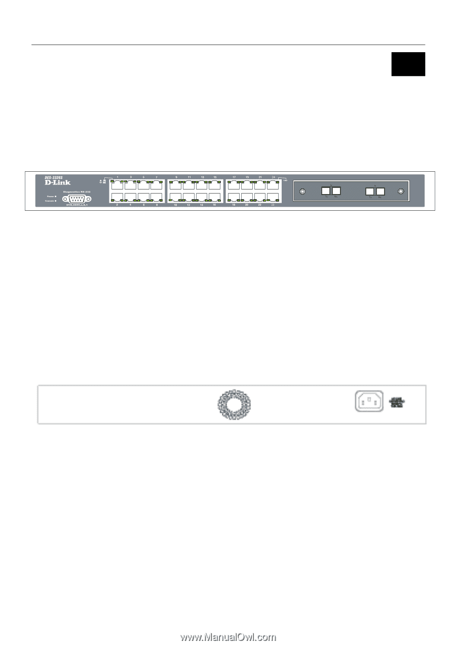
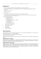
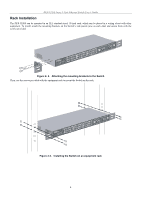
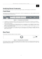
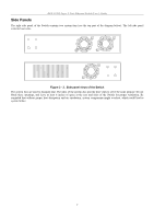
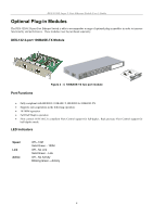
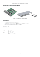
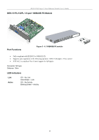
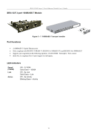
DES-3226S Layer 2 Fast Ethernet Switch User's Guide 3 Identifying External Components This chapter describes the front panel, rear panel, optional plug-in modules, and LED indicators of the DES-3226S. Front Panel The front panel of the Switch consists of LED indicators, an RS-232 communication port, a slide-in module slot, and 24 (10/100 Mbps) Ethernet/Fast Ethernet ports. Figure 3 - 1. Front panel view of the Switch • Comprehensive LED indicators display the status of the Switch and the network (see the LED Indicators section below). • An RS-232 DCE console port for setting up and managing the Switch via a connection to a console terminal or PC using a terminal emulation program. • A front-panel slide-in module slot for Gigabit Ethernet ports can accommodate a 2-port 1000BASE-T Gigabit Ethernet module, a 2-port 1000BASE-SX Gigabit Ethernet module, a 2-port 1000BASE-LX Gigabit Ethernet module, or a 2-port GBIC-based Gigabit Ethernet module. • Twenty-four high-performance, NWay Ethernet ports all of which operate at 10/100 Mbps with Auto-MDIX function for connections to end stations, servers and hubs. All ports can auto-negotiate between 10Mbps or 100Mbps, full or half duplex, and flow control. Rear Panel The rear panel of the Switch contains an AC power connector. Figure 3 - 2. Rear panel view of the Switch The AC power connector is a standard three-pronged connector that supports the power cord. Plug-in the female connector of the provided power cord into this socket, and the male side of the cord into a power outlet. Supported input voltages range from 100 ~ 240 VAC at 50 ~ 60 Hz. 6
-
 1
1 -
2
-
3
-
 4
4 -
 5
5 -
 6
6 -
 7
7 -
 8
8 -
 9
9 -
 10
10 -
 11
11 -
 12
12 -
 13
13 -
 14
14 -
15
-
16
-
17
-
18
-
19
-
20
-
21
-
22
-
23
-
24
-
25
-
26
-
27
-
28
-
29
-
30
-
31
-
32
-
33
-
34
-
35
-
36
-
37
-
38
-
39
-
40
-
41
-
42
-
43
-
44
-
45
-
46
-
47
-
48
-
49
-
50
-
51
-
52
-
53
-
54
-
55
-
56
-
57
-
58
-
59
-
60
-
61
-
62
-
63
-
64
-
65
-
66
-
67
-
68
-
69
-
70
-
71
-
72
-
73
-
74
-
75
-
76
-
77
-
78
-
79
-
80
-
81
-
82
-
83
-
84
-
85
-
86
-
87
-
88
-
89
-
90
-
91
-
92
-
93
-
94
-
95
-
96
-
97
-
98
-
99
-
100
-
101
-
102
-
103
-
104
-
105
-
106
-
107
-
108
-
109
-
110
-
111
-
112
-
113
-
114
-
115
-
116
-
117
-
118
-
119
-
120
-
121
-
122
-
123
-
124
 |
 |