D-Link DES-3226SM Product Manual - Page 51
Stacking Information, Unit ID, MAC Address, Start Port, Port Range, Version, STACK, Stack No.
 |
UPC - 790069247118
View all D-Link DES-3226SM manuals
Add to My Manuals
Save this manual to your list of manuals |
Page 51 highlights
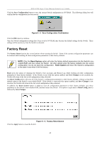
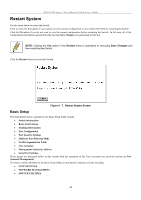
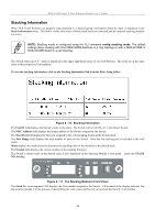
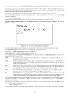
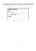
DES-3226S Layer 2 Fast Ethernet Switch User's Guide Stacking Information When DES-3226S Switches are properly interconnected in a stacked group, information about the stack is displayed in the Stack Information menu. This link is visible only when a Switch stack has been connected and the optional stacking modules are active. NOTE: Stacking mode is configured using the CLI command config stacking mode. The default settings allow stacking with other DES-3226S Switches in a ring topology or with a DGS-3212SR or DGS-3312SR Switch in a star topology. The Switch stack (up to 8 − total) is displayed in the upper right-hand corner of you web-browser. The icons are in the same order as their respective Unit numbers. To view the stacking information, click on the Stacking Information link from the Basic Setup folder: Figure 6 - 10. Stacking Information The Unit ID field displays the Switch's order in the stack. The Switch with a Unit ID of 1 is the Master Switch. The MAC Address field displays the unique address of the Switch assigned by the factory. The Start Port field displays the first port assigned to the corresponding Switch in the Switch stack. The Port Range field displays the total number of ports on the Switch. Note that the stacking port is included in the total count. Mode displays the method used to determine the stacking order of the Switches in the Switch stack. The Version field displays the version number of the stacking firmware. The Switch's current order in the Switch stack is also displayed on the Stacking Module's front panel − under the STACK NO. heading: Figure 6 - 11. The Stacking Module's Front Panel The Stack No. seven-segment LED displays the Unit number assigned to the Switch. A 0 (a zero) in the display indicates that the stacking module is in the process of determining the stack status and has not yet resolved the Switch's Unit number. 48
-
 1
1 -
2
-
3
-
4
-
5
-
6
-
7
-
8
-
9
-
10
-
11
-
12
-
13
-
14
-
15
-
16
-
17
-
18
-
19
-
20
-
21
-
22
-
23
-
24
-
25
-
26
-
27
-
28
-
29
-
30
-
31
-
32
-
33
-
34
-
35
-
36
-
37
-
38
-
39
-
40
-
41
-
42
-
43
-
44
-
45
-
 46
46 -
 47
47 -
 48
48 -
 49
49 -
 50
50 -
 51
51 -
 52
52 -
 53
53 -
 54
54 -
 55
55 -
 56
56 -
57
-
58
-
59
-
60
-
61
-
62
-
63
-
64
-
65
-
66
-
67
-
68
-
69
-
70
-
71
-
72
-
73
-
74
-
75
-
76
-
77
-
78
-
79
-
80
-
81
-
82
-
83
-
84
-
85
-
86
-
87
-
88
-
89
-
90
-
91
-
92
-
93
-
94
-
95
-
96
-
97
-
98
-
99
-
100
-
101
-
102
-
103
-
104
-
105
-
106
-
107
-
108
-
109
-
110
-
111
-
112
-
113
-
114
-
115
-
116
-
117
-
118
-
119
-
120
-
121
-
122
-
123
-
124
 |
 |