D-Link DES-3226SM Product Manual - Page 20
Connecting the Switch
 |
UPC - 790069247118
View all D-Link DES-3226SM manuals
Add to My Manuals
Save this manual to your list of manuals |
Page 20 highlights
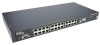
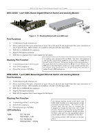
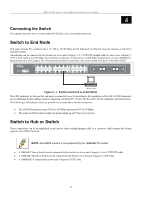
DES-3226S Layer 2 Fast Ethernet Switch User's Guide 4 Connecting the Switch This chapter describes how to connect the DES-3226S to your Fast Ethernet network. Switch to End Node End nodes include PCs outfitted with a 10, 100 or 10/100 Mbps RJ-45 Ethernet/Fast Ethernet Network Interface Card (NIC) and most routers. An end node can be connected to the Switch via a two-pair Category 3, 4, 5 UTP/STP straight cable (be sure to use Category 5 UTP or STP cabling for 100 Mbps Fast Ethernet connections. Connections to 1000 Mbps Gigabit ports on the 1000BASE-T Module must also use Category 5e). The end node should be connected to any of the twenty-four ports of the DES-3226S. Figure 4 - 1. Switch connected to an End Node The LED indicators for the port the end node is connected to are lit according to the capabilities of the NIC. If LED indicators are not illuminated after making a proper connection, check the PC's LAN card, the cable, Switch conditions, and connections. The following LED indicator states are possible for an end node to Switch connection: • The 100 LED indicator comes ON for a 100 Mbps and stays OFF for 10 Mbps. • The Link/Act LED indicator lights up upon hooking up a PC that is powered on. Switch to Hub or Switch These connections can be accomplished at any port in either straight-through cable or a crossover cable because the Switch supports Auto-MDIX function. NOTE: Auto-MDIX function is not supported by the 100BASE-TX module. • A 10BASE-T hub or Switch can be connected to the Switch via a two-pair Category 3, 4 or 5 UTP/STP cable. • A 100BASE-TX hub or Switch can be connected to the Switch via a two-pair Category 5 UTP cable. • A 1000BASE-T connections use two-pair Category 5e UTP cable. 17
-
 1
1 -
2
-
3
-
4
-
5
-
6
-
7
-
8
-
9
-
10
-
11
-
12
-
13
-
14
-
 15
15 -
 16
16 -
 17
17 -
 18
18 -
 19
19 -
 20
20 -
 21
21 -
 22
22 -
 23
23 -
 24
24 -
 25
25 -
26
-
27
-
28
-
29
-
30
-
31
-
32
-
33
-
34
-
35
-
36
-
37
-
38
-
39
-
40
-
41
-
42
-
43
-
44
-
45
-
46
-
47
-
48
-
49
-
50
-
51
-
52
-
53
-
54
-
55
-
56
-
57
-
58
-
59
-
60
-
61
-
62
-
63
-
64
-
65
-
66
-
67
-
68
-
69
-
70
-
71
-
72
-
73
-
74
-
75
-
76
-
77
-
78
-
79
-
80
-
81
-
82
-
83
-
84
-
85
-
86
-
87
-
88
-
89
-
90
-
91
-
92
-
93
-
94
-
95
-
96
-
97
-
98
-
99
-
100
-
101
-
102
-
103
-
104
-
105
-
106
-
107
-
108
-
109
-
110
-
111
-
112
-
113
-
114
-
115
-
116
-
117
-
118
-
119
-
120
-
121
-
122
-
123
-
124
 |
 |
