D-Link DES-3226SM Product Manual - Page 26
Swap a Master from a Stack
 |
UPC - 790069247118
View all D-Link DES-3226SM manuals
Add to My Manuals
Save this manual to your list of manuals |
Page 26 highlights
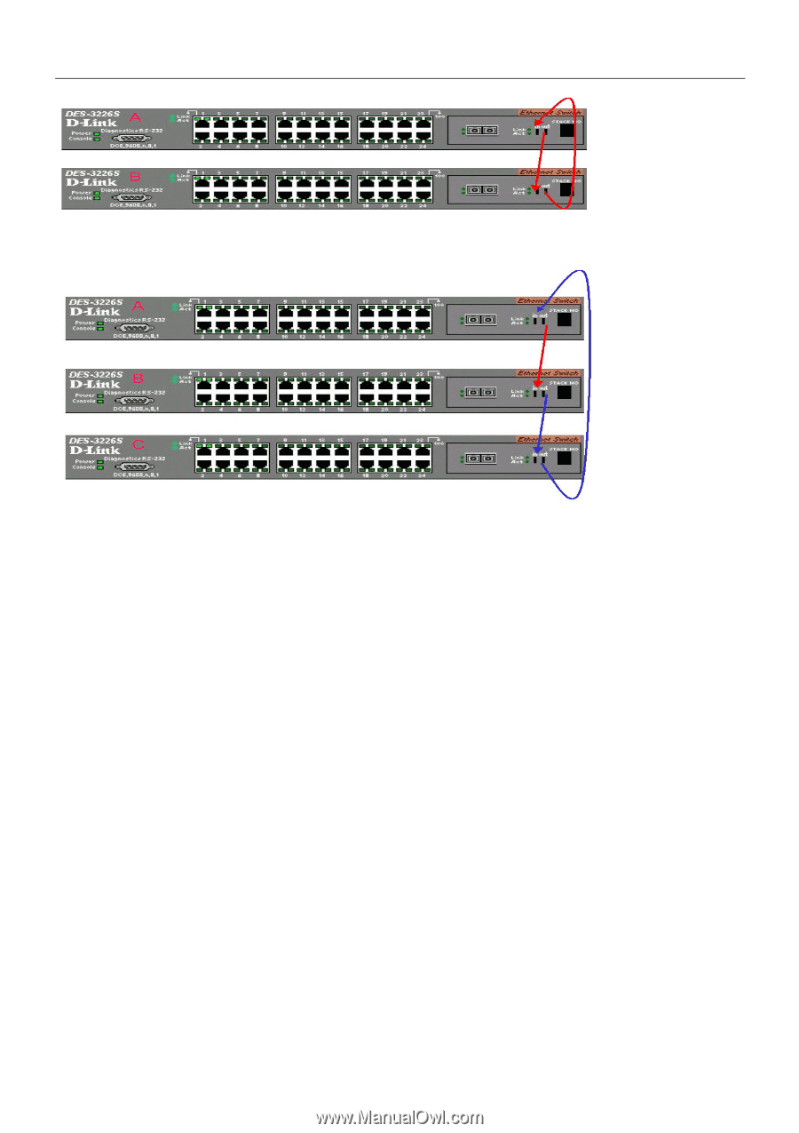
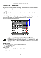
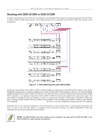
DES-3226S Layer 2 Fast Ethernet Switch User's Guide Switch C is added to the existing stack where Switch A is the designated master. Power off all devices and securely place Switch C in the slot beneath Switch B. Adjust stacking cable connections so the OUT port on Switch B connects the IN port on Switch C and the OUT port of Switch C connects to the IN port of Switch A. Power on the entire stack. The new stacking arrangement is recognized and the new relationship is negotiated. Switch A retains status as the master of the stack, Switch C is in auto mode and therefore functions as a slave. The stack is ready for operation. Swap a Master from a Stack Let's assume the stack arrangement in the previous example has a problem that requires the master unit, Switch A, to be replaced. In this case, we can preserve all the same configuration settings by downloading the previously saved configuration files to the replacement Switch. Before disconnecting the network connections of the original master unit, label each Ethernet cable so they can be placed in the same port number in the replacement Switch. Then remove the device from the rack. Place the replacement Switch in the same slot. Power on the new Switch and attach a console cable to it. Configure the new unit to be a master and save the settings. Connect the Ethernet cable needed to access the TFTP server containing the saved configuration files of the previous master unit. Download the saved configuration files, use the command: download configuration Save the new settings and power off the Switch. Now the stacking connections and Ethernet connections can be completed exactly as before. Reconnect the stacking cables and Ethernet connections and power on the entire stack. The stack should now function as before with all the configuration settings intact. 23
-
 1
1 -
2
-
3
-
4
-
5
-
6
-
7
-
8
-
9
-
10
-
11
-
12
-
13
-
14
-
15
-
16
-
17
-
18
-
19
-
20
-
 21
21 -
 22
22 -
 23
23 -
 24
24 -
 25
25 -
 26
26 -
 27
27 -
 28
28 -
 29
29 -
 30
30 -
 31
31 -
32
-
33
-
34
-
35
-
36
-
37
-
38
-
39
-
40
-
41
-
42
-
43
-
44
-
45
-
46
-
47
-
48
-
49
-
50
-
51
-
52
-
53
-
54
-
55
-
56
-
57
-
58
-
59
-
60
-
61
-
62
-
63
-
64
-
65
-
66
-
67
-
68
-
69
-
70
-
71
-
72
-
73
-
74
-
75
-
76
-
77
-
78
-
79
-
80
-
81
-
82
-
83
-
84
-
85
-
86
-
87
-
88
-
89
-
90
-
91
-
92
-
93
-
94
-
95
-
96
-
97
-
98
-
99
-
100
-
101
-
102
-
103
-
104
-
105
-
106
-
107
-
108
-
109
-
110
-
111
-
112
-
113
-
114
-
115
-
116
-
117
-
118
-
119
-
120
-
121
-
122
-
123
-
124
 |
 |