D-Link DES-3226SM Product Manual - Page 21
Switch Stack Connections, 10BASE-T Device
 |
UPC - 790069247118
View all D-Link DES-3226SM manuals
Add to My Manuals
Save this manual to your list of manuals |
Page 21 highlights
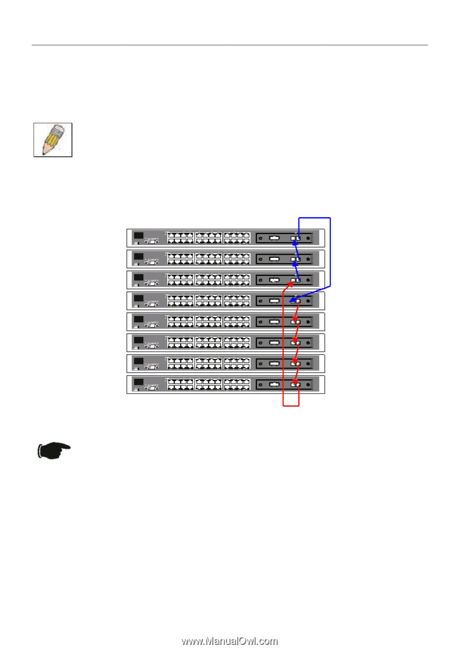
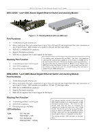
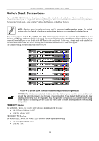
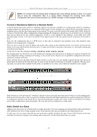
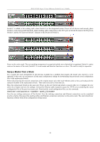
DES-3226S Layer 2 Fast Ethernet Switch User's Guide Switch Stack Connections Up to eight DES-3226S Switches (with optional stacking modules installed) can be stacked into a Switch stack that can then be configured and managed as a single unit. The management agent of the master Switch can configure and manage all of the Switches in a Switch stack − using a single IP address (the IP address of the Master Switch). NOTE: Stacking mode is configured using the CLI command config stacking mode. The default settings allow the Switch to function as a standalone device or as a member of a stacked group. The stacking ports are marked IN and OUT. The IEEE 1394 compliant cable must be connected from an IN port on one Switch to an OUT port on the next Switch in the stack. The last two Switches (at the top and bottom of the stack) must also be connected from the IN port on one Switch to the OUT port on the other Switch. In this way, a loop is made such that all of the Switches in the Switch stack have the IN stacking port connected to another Switch's OUT stacking port. An example stacking port interconnection is shown below: Figure 4 - 2. Switch Stack connections between optional stacking modules NOTICE: If a link between stacked Switches fails the stacked group must be connected to work around the failed link. As with any changes in the composition of the stacked Switch group, the new stacking relationship must be negotiated. Any change to the composition of a stacked Switch group or any failure of a stacking port will cause the entire stack to restart and negotiate the new stacking composition. 10BASE-T Device For a 10BASE-T device, the Switch's LED indicators should display the following: • 100 LED speed indicator is OFF. • Link/Act indicator is ON. 100BASE-TX Device For a 100BASE-TX device, the Switch's LED indicators should display the following: • 100 LED speed indicator is ON. • Link/Act is ON. 18
-
 1
1 -
2
-
3
-
4
-
5
-
6
-
7
-
8
-
9
-
10
-
11
-
12
-
13
-
14
-
15
-
 16
16 -
 17
17 -
 18
18 -
 19
19 -
 20
20 -
 21
21 -
 22
22 -
 23
23 -
 24
24 -
 25
25 -
 26
26 -
27
-
28
-
29
-
30
-
31
-
32
-
33
-
34
-
35
-
36
-
37
-
38
-
39
-
40
-
41
-
42
-
43
-
44
-
45
-
46
-
47
-
48
-
49
-
50
-
51
-
52
-
53
-
54
-
55
-
56
-
57
-
58
-
59
-
60
-
61
-
62
-
63
-
64
-
65
-
66
-
67
-
68
-
69
-
70
-
71
-
72
-
73
-
74
-
75
-
76
-
77
-
78
-
79
-
80
-
81
-
82
-
83
-
84
-
85
-
86
-
87
-
88
-
89
-
90
-
91
-
92
-
93
-
94
-
95
-
96
-
97
-
98
-
99
-
100
-
101
-
102
-
103
-
104
-
105
-
106
-
107
-
108
-
109
-
110
-
111
-
112
-
113
-
114
-
115
-
116
-
117
-
118
-
119
-
120
-
121
-
122
-
123
-
124
 |
 |