Epson EPL-N1200 Service Manual
Epson EPL-N1200 Manual
 |
View all Epson EPL-N1200 manuals
Add to My Manuals
Save this manual to your list of manuals |
Epson EPL-N1200 manual content summary:
- Epson EPL-N1200 | Service Manual - Page 1
EPSON TERMINAL PRINTER EPL-N1200 SERVICE MANUAL EPSON 4006838 - Epson EPL-N1200 | Service Manual - Page 2
. Reproduction of any part of this manual in any form whatsoever without SEIKO EPSON's express written permission is forbidden. The contents of this manual are subjects to change without notice. All efforts have been made to ensure the accuracy of the contents of this manual. However, should any - Epson EPL-N1200 | Service Manual - Page 3
TESTING AS DICTATED WITHIN THIS MANUAL, DO NOT CONNECT THE UNIT TO A POWER SOURCE UNTIL INSTRUCTED TO DO SO. WHEN THE POWER SUPPLY CABLE MUST BE CONNECTED, USE EXTREME CAUTION IN WORKING ON POWER SUPPLY AND OTHER ELECTRONIC COMPONENTS. WA FINING 1. REPAIRS ON EPSON PRODUCT SHOULD BE PERFORMED ONLY - Epson EPL-N1200 | Service Manual - Page 4
. There is no possibility of danger from the laser, provided the printer is operated according to the instructions in this manual provided. Since radiation emitted by the laser is completely confined within protective housings, the laser beam cannot escape from the machine during any phase of user - Epson EPL-N1200 | Service Manual - Page 5
er 790 f 20 run. I Laser Safety Labels [Label on rear printer case] A laser safety labels is attached on the outside of the printer shown below. For United State This laser product conforms to the applicable requirement of 21 CFR Chapter I, subchapter J. SEIKO EPSON CORP. Hirooka Office 80 - Epson EPL-N1200 | Service Manual - Page 6
For Europe [Label inside printer] The following laser safely label will be attached inside the printer as shown below. For Denmark, Finland, Sweden, and Norway - Epson EPL-N1200 | Service Manual - Page 7
Describes the theory of printer operation. CHAPTER 3. DISASSEMBLY AND ASSEMBLY Includes a step-by-step guide for product disassembly and assembly. CHAPTER 4. ADJUSTMENTS Includes a step-by-step guide for adjustment. CHAPTER 5. TROUBLESHOOTING Provides Epson-approved techniques for adjustment - Epson EPL-N1200 | Service Manual - Page 8
REVISION SHEET I Revision I Issue Date Rev. A December 9 1996 Revision Page 1st issue - vii - - Epson EPL-N1200 | Service Manual - Page 9
TABLE OF CONTENTS CHAPTER 1. CHAPTER 2. CHAPTER 3. CHAPTER 4. CHAPTER 5. CHAPTER 6. APPENDIX GENERAL DESCRIPTION OPERATING PRINCIPLES DISASSEMBLY AND ASSEMBLY ADJUSTMENTS TROUBLESHOOTING MAINTENANCE . . . - VIII - - Epson EPL-N1200 | Service Manual - Page 10
Specification for Consumable (Imaging Cartridge 1-6 1.2.8 Physical Specifications 1.4 OPERATING INSTRUCTIONS 1-22 1.4.1 Control Panel 1-22 1.4.2 SelecType Functions 1-24 1.4.3 Service Mode 1- Resolution Improvement Technology 1-36 1.4.8 Printer Initialization 1-37 1.4.9 Toner Save Mode 1-38 - Epson EPL-N1200 | Service Manual - Page 11
1-44 1.5.9 Imaging Cartridge 1-44 1.5.10 Lower Paper Cassette 1-45 List of Figures Figure 1-1. EPL-N1200 Exterior View 1-1 Figure 1-13. BiRITech Effect 1-36 Figure 1-14. RITech Adjustment 1-36 Figure 1-15. Toner Save Mode 1-38` Figure 1-16. Component Layout 1-39 Figure 1-17. C205 Main - Epson EPL-N1200 | Service Manual - Page 12
List of Tables Table 1-1. EPL-N1200 Options 1-2 Table 1-2. Paper Feed Methods 1-3 Table 1-3. Paper Types 1-3 Table 1-4. Special Papers Usability 1-4 Table 1-5. Electrical Specifications 1-5 Table 1-6. Differences between EPSON GL/2 and GL/2 in the HP LaserJet 4 Emulation 1-7 Table 1-7. Built- - Epson EPL-N1200 | Service Manual - Page 13
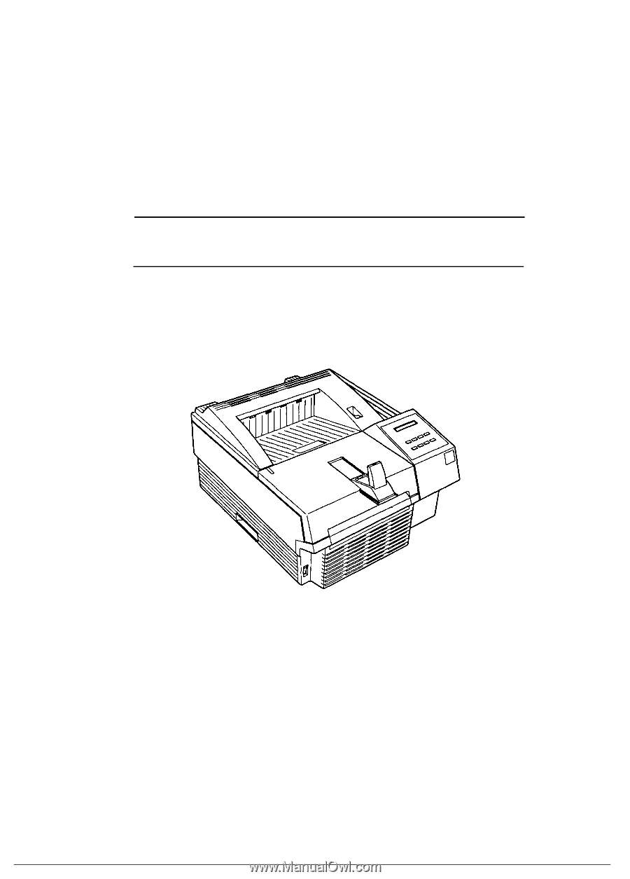
EPL-N1200 Service Manual General Description 1.1 FEATURES The EPSON® EPL-N1200 is a non-impact page printer that combines a semi-conductor laser with electro-photographic technology. Resolution is 600/300 DPI and print speed is 12 PPM. The main features are: o Upward compatibility with the EPL- - Epson EPL-N1200 | Service Manual - Page 14
EPL-N1200 Service Manual Table 1-1 lists optional units available for the EPL-N1200. Table 1-1. EPL-N1200 Options Cat. No. Description Note C83219V EPSONScript Level 2 ROM Module Supports Current loop cable 32 KB serial interface card Toner cartridge - For C82334V For C82334V For C82334V - - Epson EPL-N1200 | Service Manual - Page 15
EPL-N1200 Service Manual 1.2 SPECIFICATIONS This section provides statistical data for the EPL-N1200. General Description 1.2.1 Basic Specifications Print method: Laser beam scanning and dry electro-photography Resolution: 600 DPI Printing speed: 12 PPM (letter/A4) First print time (A4/LT): - Epson EPL-N1200 | Service Manual - Page 16
EPL-N1200 Service Manual P: Possible, but better avoided. N: Not supported. Labels Card Stock Letterhead P P R N 1-2. Note: The actual printable area depends on the printer mode. Harmonic noise: Less than 36 dB(A) standby photo-conductor (OPC), toner, and plastic materials 4.00mm Printable Area 4. - Epson EPL-N1200 | Service Manual - Page 17
EPL-N1200 Service Manual problem requiring replacement or service . MTBF (Mean Time Between Failures): Jam rate: Feed failure: Multiple-sheet feeding: Paper curl height: Leading edge bending (1 cm or more): MTTR (Mean Time To Repair (Including Imaging Cartridge) Temperature: 10 Printer - Epson EPL-N1200 | Service Manual - Page 18
EPL-N1200 Service Manual 1.2.6 Applicable Standards (without any electrical optional unit) Safety Standards 120 VAC model: 230 VAC model (Europe): UL 1950 Deviation 3, CSA 22.2 No.950 Deviation 3 EN 60950 (IEC950), NEMKO (IEC950), CE marking (low voltage directive) Safety Regulations (Laser - Epson EPL-N1200 | Service Manual - Page 19
EPL-N1200 Service Manual General Description 1.2.9 Software Specifications Built-in modes: HP LaserJet4 emulation ( PCL® 5e) EPSON GL/2 mode (LJ4-GL/2 mode and GL-like mode) FX (FX-870/1170,LX-100) emulation mode ESC/P2 (Stylus800/1000) mode I239X ( IBM 2390/2391 Plus emulation) EPSON - Epson EPL-N1200 | Service Manual - Page 20
Description EPL-N1200 Service Manual Table 1-7. Built-in Fonts (Scalable Fonts) Resident Fonts EPSON Roman EPSON Sans serif EPSON Prestige EPSON Script EPSON Gothic EPSON Presentor EPSON Orator SWM Bold Italic SWM SWA SWM V: Supported, -: Not Supported Applicable Mode HP LJ4 GL/2 ESC/P 2 FX - Epson EPL-N1200 | Service Manual - Page 21
EPL-N1200 Service Manual General Description Table 1-7. Built-in Fonts (Scalable Fonts; Cont') Resident Fonts Courier Courier Courier Courier Letter Gothic Letter Gothic Letter Gothic Ext. Graph SWC Bold SWC Italic SWC Bold Italic SWC Roman SWC Bold SWC Italic SWC V: Supported, -: Not - Epson EPL-N1200 | Service Manual - Page 22
General Description EPL-N1200 Service Manual Font Symbol Sets and Character Tables HP LaserJet 4 Mode (bitmap 8859-2 ISO Spanish Swedish Portuguese PsMath IBM Portuguese WiTurkish DeskTop PcTk437 Windows PsText IBM-DN McText PcMultilingual VeUS PiFont PcE.Europe WiAnsi TWingdings - Epson EPL-N1200 | Service Manual - Page 23
EPL-N1200 Service Manual General Description 1.2.10 Lower Paper Cassette (Option) Paper Type: Plain paper, such as copier paper Power Supply: 5 V DCand 24 VDC are supplied by the printer Dimensions and Weight: (Width × Depth × Height) Lower paper cassette entire housing; 405 × 477 × 107 - Epson EPL-N1200 | Service Manual - Page 24
B s Parallel interface C s Serial interface on optional LocalTalk/Serial module s LocalTalk interface on optional LocalTalk/Serial module EPL-N1200 Service Manual 1.3.1 Parallel Interfaces There are two parallel interfaces: parallel interface B and parallel interface C. Each interface has his own - Epson EPL-N1200 | Service Manual - Page 25
EPL-N1200 Service Manual General Description Table 1-8. Parallel Interfaces Pin Assignment Parallel-B Pin No. Signal Name signal. I TLOheWS. TROBE signal is ignored when this signal is This level goes LOW when the printer is: out of paper O paper jam in error state off line - Same as for pins - Epson EPL-N1200 | Service Manual - Page 26
General Description EPL-N1200 Service Manual 1.3.1.2 Nibble (Reverse), ECP Mode The reverse mode for EPL-N1200 supports the IEEE-P1284 nibble mode. This printer can run in reverse mode, in which the printer can inform the computer of its status by EJL and PJL commands. System: Nibble mode of - Epson EPL-N1200 | Service Manual - Page 27
EPL-N1200 Service Manual Compatibility Mode Forward Data Transfer STROBE ACK and BUSY Forward Idle General Description Terminate SLCT IN=HIGH Failed Negotiation SLCT IN=LOW ERR=HIGH No - Epson EPL-N1200 | Service Manual - Page 28
General Description Figure 1-5 shows the timing chart for negotiation. EPL-N1200 Service Manual DATA SEL-IN STROBE AUTO-FEED ACKNLG BUSY PE SLCT ERROR 00h or 04h Peripheral Busy Status Current Peripheral Status Current Peripheral Status Note1 Note 2 - Epson EPL-N1200 | Service Manual - Page 29
EPL-N1200 Service Manual General Description DATA SEL-IN STROBE AUTO-FEED Note 3 ACKNLG BUSY Peripheral Busy Status PE Note 1 SLCT ERROR Note 2 Note 1 Peripheral Busy Status Current Peripheral - Epson EPL-N1200 | Service Manual - Page 30
General Description EPL-N1200 Service Manual 1.3.2 Optional Serial Interface (LocalTalk/Serial Module be combined with DTR control) DTR control (can be combined with X-ON/X-OFF) Transfer speed: 300, 600, 1200, 2400, 4800, 9600, 19200, 38400, or 57600 BPS Note 1: For RS-232C signal level, speeds - Epson EPL-N1200 | Service Manual - Page 31
EPL-N1200 Service Manual General Description Table 1-10. Serial Interface Pin Assignments Pin No. RS-232C Current Loop Description ^ Signal Name I/O Signal Name I/O ^ Signal output by the printer. When the DTR signals HIGH, the RXD signal can be received by the printer. The SelecType - Epson EPL-N1200 | Service Manual - Page 32
General Description EPL-N1200 Service Manual Handshaking When the vacant area for data in the input buffer drops to 256 bytes, the printer outputs an X-OFF code or sets the DTR signal level to LOW, indicating that the printer cannot receive more data. Once the vacant area for data in the buffer - Epson EPL-N1200 | Service Manual - Page 33
EPL-N1200 Service Manual General Description 1.3.3 Optional LocalTalk Interface (LocalTalk/Serial Module) The 1 DTR O Signal output by the printer. When the DTR signals HIGH, the RXD signal can be received by the printer. 2 CTS I The printer transmits the data through TXD while CTS is - Epson EPL-N1200 | Service Manual - Page 34
EPL-N1200 Service Manual General Description Buttons o On Line o Manual Feed (On Line + ALT) o Item o Page Size (Item+ ALT) o Paper Source (Menu+ ALT) o ALT o↑ o ↓ (↑ + ALT) o Enter o Form Feed o Continue o SelecType o Menu o Value o Enter o RESET (Continue + ALT) Switches the printer between on- - Epson EPL-N1200 | Service Manual - Page 35
Description EPL-N1200 Service Manual 1.4 OPERATING INSTRUCTIONS This section describes the functions performed through the control panel, such as test print, hexadecimal dump, and SelecType. 1.4.1 Control Panel The printer control panel gives you easy control over most common printer operations - Epson EPL-N1200 | Service Manual - Page 36
EPL-N1200 Service Manual 1.4.2 SelecType Functions SelecType function on the printer control panel allows the user to control most of the printer's functions, such as printing test pages, selecting a paper size, and changing the printer Resident, SIMM, Download Font Number , French2, Windows 5 to - Epson EPL-N1200 | Service Manual - Page 37
EPL-N1200 Service Manual General Description Table 1-12. SelecType Functions (Cont.) Menu (Changed by Menu button) ESCP2 Menu (Cont.) FX Menu I239X Menu Rev. A Item (Changed by Item button) - Epson EPL-N1200 | Service Manual - Page 38
General Description EPL-N1200 Service Manual Table 1-12. SelecType Functions (Cont.) Menu ( Sprache*18) Ling*18) Leng*18) Sprak*18) Sprog*18) Taai*18) Kieli*18) Idiom*18) Panel Lock*1`7) Toner*8) Toner Count Clear Page Count*8) LJ4, ESCP2, FX, I239X, PS*4), GL2, Auto LJ4, ESCP2, FX, I239X, PS*4), - Epson EPL-N1200 | Service Manual - Page 39
EPL-N1200 Service Manual General Description ^ SelecType Init Table 1-12. SelecType Functions (Cont.) Menu , Minimum Serial Menu*6) Word Length 8, 7 Baud Late 9600, 19200, 38400, 57600, 300, 600, 1200, 2400, 4800 Parity None, Even, Add Stop Bit 1, 2 Xon/Xoff*7) On, Off, Robst DTR - Epson EPL-N1200 | Service Manual - Page 40
General Description EPL-N1200 Service Manual *10) Can be selected only when Type-B I/F is installed. *11) Can be selected only when the lower paper both setting the item and the value. *21) After resetting the value, warm boot or restart the printer to make the value effective. 1-28 Rev. A - Epson EPL-N1200 | Service Manual - Page 41
EPL-N1200 Service Manual General Description 1.4.3 Service Mode This printer has the following three service modes: s Hexadecimal Dump Mode s EEPROM Format s Error Recovery 1.4.3.1 Hexadecimal Dump Mode Hexadecimal dump mode is a useful tool for troubleshooting data control problems toner counter - Epson EPL-N1200 | Service Manual - Page 42
General Description EPL-N1200 Service Manual 1.4.3.3 Error Recovery The LCD on the control panel unit indicates the printer status and error code if the printer has fatal error. CPU reset This function can be used without restarting the printer to attempt to recover from a fatal error (" E*****" - Epson EPL-N1200 | Service Manual - Page 43
EPL-N1200 Service Manual General Description 1.4.4 Display of Messages This printer displays three types of messages on the LCD: status messages, error messages, and power on messages. 1.4.4.1 Status Messages The LCD panel normally indicates the printer . Detected toner low (remaining toner is 0 - Epson EPL-N1200 | Service Manual - Page 44
EPL-N1200 Service Manual 1.4.4.2 Error Messages If any of the following errors occurs, it will be displayed on the LCD panel. The error must be cleared immediately using the measures shown in the following table. Table 1-15. Error Messages Message Paper Jam Feed Jam Printer Open Manual - Epson EPL-N1200 | Service Manual - Page 45
EPL-N1200 Service Manual General Description 1.4.4.3 Warning Message If any of the following warnings occurs, it will be displayed on the LCD panel. Table 1-16. Warning Messages Message Menus Locked Check Paper Size Image Optimum Toner , the printer uses a lower print quality. Remaining toner is 0 - Epson EPL-N1200 | Service Manual - Page 46
General Description EPL-N1200 Service Manual 1.4.5 Multi-user and Multi-emulation This printer has a multi-user and multi-emulation functions. It can be connected simultaneously to and receive print codes from up to four different hosts or networks ( - Epson EPL-N1200 | Service Manual - Page 47
EPL-N1200 Service Manual General Description 1.4.6 Emulation Mode Switch Function This section describes the emulation mode switch function. 1.4.6.1 Emulation Switch by SPL The four types of emulation switch functions described below are available on this printer switch between EPSON Script and - Epson EPL-N1200 | Service Manual - Page 48
General Description EPL-N1200 Service Manual 1.4.7 Bi Resolution Improvement Technology The EPL-N1200 printer has BiRITech (Bi the BiRITech effect depends on the toner condition, it should be adjusted when the imaging cartridge is replaced or after the imaging cartridge is used for a long time. - Epson EPL-N1200 | Service Manual - Page 49
EPL-N1200 Service Manual General Description 1.4.8 Printer Initialization There are three ways to initialize this printer before entering the on line state. Reset Procedure This is performed by holding down the Alt and Reset buttons. The reset procedure aborts printing on - Epson EPL-N1200 | Service Manual - Page 50
General Description EPL-N1200 Service Manual 1.4.9 Toner Save Mode The Tonere Save Mode uses about 50 % less toner than the normal. The printer saves toner by substituting a gray shade for the black inside of characters. The outsides of the characters are still printed in full black. Upper Edge - Epson EPL-N1200 | Service Manual - Page 51
EPL-N1200 Service Manual General Description 1.5 MAIN COMPONENTS To simplify maintenance and repair, the main components of the EPL-N1200 has been circuit board t Optical Unit Printhead unit t Fusing Unit t Imaging Cartridge t Lower Paper Cassette Unit (optional) Only for specific models. - Epson EPL-N1200 | Service Manual - Page 52
General Description EPL-N1200 Service Manual 1.5.1 C205 MAIN Board The C205 MAIN board is a Main Figure 1-17. C205 Main Board There are two types of C205 MAIN boards used as after service parts. The following table shows differences between them. Table 1-17. Differences in Components for the C205 - Epson EPL-N1200 | Service Manual - Page 53
EPL-N1200 Service Manual General Description 1.5.2 C173 PROG Board The C173 PROG board, which control panel includes a 20 column × 1 row LCD panel, which provides many functions for the printer (e.g., displaying error messages or printer operation status). Figure 1-19. Control Panel Rev. A 1-41 - Epson EPL-N1200 | Service Manual - Page 54
General Description EPL-N1200 Service Manual 1.5.4 Engine Controller Board The engine controller board consists of an M37451 8-bit CPU (including a P-ROM) and a gate array. The board controls laser scanning (the polygon mirror drive motor), image synchronization, laser beam pulse width, and power. - Epson EPL-N1200 | Service Manual - Page 55
EPL-N1200 Service Manual General Description 1.5.6 High-Voltage Supply Board The high-voltage the laser diode (semi-conductor laser), the mirror motor (scanner motor) which drives the polygon mirror for laser scanning, and several mirrors and lenses. The laser beam generated by the laser diode - Epson EPL-N1200 | Service Manual - Page 56
General Description EPL-N1200 Service Manual 1.5.8 Fusing Unit The fusing unit fixes the toner to the paper using heat Cartridge The core mechanisms of the printing process, such as charging, developing, and cleaning, are integrated into this imaging cartridge. Figure 1-25. Imaging Cartridge - Epson EPL-N1200 | Service Manual - Page 57
EPL-N1200 Service Manual General Description 1.5.10 Lower Paper Cassette The optional lower paper cassette allows you to feed up to an additional 500 sheets of A4 or letter-size paper into this printer. You can add the two lower papaer cassettes for the printer. Figure 1-26. Lower Paper Cassette - Epson EPL-N1200 | Service Manual - Page 58
Print Process 2-2 2.1.1.1 Paper Feeding 2-3 2.1.1.2 Drum Charge 2-4 2.1.1.3 Laser Exposure 2-5 2.1.1.4 Development 2-5 2.1.1.5 Drum Cleaning 2-5 2.1.1.6 Image Transfer 2-6 2.1.1.7 Fusing 2-6 2.1.1.8 Paper Exit 2-6 2.1.1.9 Toner Empty Sensor 2-7 2.1.2 Engine Control 2-8 2.1.2.1 Main Motor - Epson EPL-N1200 | Service Manual - Page 59
Laser Exposure 2-5 Figure 2-7. Development 2-5 Figure 2-8. Image Transfer 2-6 Figure 2-9. Fusing 2-6 Figure 2-10. Toner is Enough 2-7 Figure 2-11. Tonere 12 Figure 2-18. Scanner Motor Control Circuit 2-13 Figure 2-19. Laser Diode Drive Circuit 2-13 Figure 2-20. /L DATA Generation Circuit 2-13 - Epson EPL-N1200 | Service Manual - Page 60
operating principles of the EPL-N1200 engine. Figure 2-1 shows the locations and names of the main engine components. 23 4 5 6 7 8 9 10 11 1 26 12 13 14 25 15 24 16 17 18 19 23 20 21 22 1. Paper Guide 2. Paper Empty Sensor Lever 3. Optical Unit 4. Imaging Cartridge 5. Paper Take-up - Epson EPL-N1200 | Service Manual - Page 61
Operating Principles EPL-N1200 Service Manual 2.1.1 Print Process This section describes the print process from paper feeding to paper exit. Figure 2-2 shows a diagram of the print process. Figure 2-2. Print Process Diagram 2-2 Rev. A - Epson EPL-N1200 | Service Manual - Page 62
EPL-N1200 Service Manual Operating Principles 2.1.1.1 Paper Feeding There are two methods of feeding paper into the printer. One uses signal to go HIGH, informing the engine driver that paper has been delivered. Multi-Purpose Tray (Standard Tray) The paper guide can be moved to fit against the - Epson EPL-N1200 | Service Manual - Page 63
Operating Principles EPL-N1200 Service Manual Lower Paper Cassette A maximum of 500 sheets can be Charge Drum charge is the process of charging the PC drum with static electricity before laser exposure. This printer uses a brush charge method, rather than the corona charge method, to charge the - Epson EPL-N1200 | Service Manual - Page 64
EPL-N1200 Service Manual Operating Principles 2.1.1.3 Laser Exposure Laser exposure is the process of creating an invisible static electric image on the PC drum with laser development with the developing bias voltage. No positively charged toner is transported to the PC drum, and the doctor blade - Epson EPL-N1200 | Service Manual - Page 65
Operating Principles EPL-N1200 Service Manual 2.1.1.6 Image Transfer Image transfer is the process of transferring the toner image created on the PC drum to the paper during the developing process. This printer uses the roller image transfer method, instead of corona image transfer, as the image - Epson EPL-N1200 | Service Manual - Page 66
EPL-N1200 Service Manual Operating Principles 2.1.1.9 Toner Empty Sensor Toner empty is detected by the toner empty LED and the photo sensor on the toner empty detection board. When there is enough toner in the imaging cartridge, light is not reflected from the toner empty sensor LED. When toner - Epson EPL-N1200 | Service Manual - Page 67
Operating Principles EPL-N1200 Service Manual 2.1.2 Engine Control This section describes engine control, the power supply board SW AC Power Input Interlock SW Heater Lamp Main Motor PWB-G Toner Empty Sensor PWB-S Transfer Current Change SW. Figure 2-12. Engine Controller Connecting Diagram 2-8 Rev - Epson EPL-N1200 | Service Manual - Page 68
EPL-N1200 Service Manual Operating Principles 2.1.2.1 Main Motor Functions and Control Power from the main motor (M1) drive is used for the P/C (photo conductor) drive, the developing drive, the - Epson EPL-N1200 | Service Manual - Page 69
Operating Principles 4 21 8 26 32 1 0 10 1 13 14 15 15 EPL-N1200 Service Manual 95 7 6 5 1 12 16 18 9 Figure 2-14. Gear and Roller Positions Table 2-1. Gears and Rollers No. 0 1 2 3 4 5 6 7 8 9 10 11 12 13 14 No. of Gear Teeth Roller - Epson EPL-N1200 | Service Manual - Page 70
EPL-N1200 Service Manual Operating Principles Figure 2-15 shows the main motor drive circuit. The main motor (M1) is a four-phase stepping motor. This motor is controlled by the CPU (IC1) on the engine controller board (PWB-A). The power supply board (PU1) has a stepping motor driver IC. This IC - Epson EPL-N1200 | Service Manual - Page 71
fuser temperature control operation. Temperature Normal Mode EPL-N1200 Service Manual Hot Mode Ready Ready Print Cycle (Normal the temperature of the upper fusing roller is less than 100° C (212° F) after printer power on, fusing temperature is controlled to heat the roller to 195° C (383° - Epson EPL-N1200 | Service Manual - Page 72
EPL-N1200 Service Manual Operating Principles 2.1.2.3 Scanner Mirror Motor Control Figure 2-18 controller board (C205 MAIN board). The FORCED LASER DIODE ON signal is a laser emission signal to apply the laser beam to the SOS sensor. Forced Laser Diode ON VIDEO from the Video Controller Board - Epson EPL-N1200 | Service Manual - Page 73
Operating Principles EPL-N1200 Service Manual 2.1.2.5 Bias Voltages and Laser Drive Timing Figure 2-21 is a diagram the switch be positioned at H. If the printer is used in an environment with low temperature and low humidity and a toner smear problem occurs at the age of the transparency sheets, - Epson EPL-N1200 | Service Manual - Page 74
EPL-N1200 Service Manual Figure 2-22 shows the print process. Brush Charging Laser Exposure Development PC Drum Operating Principles Image Transfer Figure 2-22. Print Process Figure 2-23 shows the start print sequence. The printer's engine starts printing when the PRINT signal is received from - Epson EPL-N1200 | Service Manual - Page 75
Operating Principles EPL-N1200 Service Manual 2.1.2.6 Power Supply Circuit Function and Safety Protection The printer's power supply board (PU1) supplies the +5 VDC and +24 VDC. The +24 VDC is used as the bias voltage supply, main motor (M1) drive, scanner - Epson EPL-N1200 | Service Manual - Page 76
EPL-N1200 Service Manual Operating Principles 2.2 VIDEO CONTROLLER OPERATION The video consists of a MB86930 (SPARKlite, 20 MHz, 32-bit bus) RISC CPU, the standard cells developed for this printer, RAMs, ROMs, and a EEPROM. Parallel-C 74ACT1284 (C29,30,31) CPU MB86930 (IC15) ROM 16M-Bits - Epson EPL-N1200 | Service Manual - Page 77
Operating Principles EPL-N1200 Service Manual Table 2-2 lists the functions of the C205 for fonts. This 1 K-bit EEPROM stores the following: Model type Printed page counter value Toner life counter value Jam counter value SelecType setting It provides working memory area for E05B17. These DRAMs - Epson EPL-N1200 | Service Manual - Page 78
EPL-N1200 Service Manual Operating Principles Print data and commands transmitted from the transmits the temporary buffer's data to the engine controller board. The E05B17 then manipulates the printer data according to the BiRITech setting. CPU MB86930 (IC15) E05A91 (IC1) Development E05A93 - Epson EPL-N1200 | Service Manual - Page 79
Operating Principles EPL-N1200 Service Manual 2.2.1.1 Reset Circuit The entire system (CPU and external devices) can be initialized if the RESET signal (CPU pin 113) is active simultaneously. This circuit uses - Epson EPL-N1200 | Service Manual - Page 80
EPL-N1200 Service Manual Operating Principles 2.2.1.3 Interrupt Control The ASIC E05A93 2.2.1.4 DRAM Management The video controller uses DRAMs for the system RAM and for the V-RAM. In this printer, four standard 512K × 8bit DRAMs are mounted in locations IC18, IC19, IC20, and IC21, providing a - Epson EPL-N1200 | Service Manual - Page 81
EPL-N1200 Service Manual the data from the E05A93, so that the printer is ready to receive more data from the 74ACT1284 is a bi-directional bus driver IC that used to satisfy the data E05B27(IC43) is used the Parallel-C interface to support, not only standard parallel interface, but also compatibility - Epson EPL-N1200 | Service Manual - Page 82
EPL-N1200 Service Manual Operating Principles 2.2.1.7 Video Interface The ASIC E05B17 (IC16) maps the commands (from the video controller) or status (from the engine controller) for printer mechanism control. Except for VIDEO, PRINT, VSINC, and HSYNC, all signals are controlled by ASIC E05A93. - Epson EPL-N1200 | Service Manual - Page 83
/Assembly 3-1 3.1.2 Tools 3-1 3.1.3 Small Parts 3-2 3.1.4 Service Checks after Repair 3-3 3.2 DISASSEMBLY AND ASSEMBLY 3-4 3.2.1 Optical Unit Removal 3-12 3.2.2.5 Paper Empty Sensor Removal 3-13 3.2.2.6 Toner End Sensor Removal 3-14 3.2.2.7 Paper Take-Up Solenoid Removal 3-15 - Epson EPL-N1200 | Service Manual - Page 84
Cover Removal 3-5 Figure 3-5. Connectors on Engine Driver Board 3-6 Figure 3-6. Engine Controller Board Removal 3-13 Figure 3-15. Paper Empty Sensor Removal 3-13 Figure 3-16. Toner End Sensor Removal 3-14 Figure 3-17. Bracket Removal 3-15 Figure 3-18 3-2 Table 3-4. Checks after Repair 3-3 - Epson EPL-N1200 | Service Manual - Page 85
EPL-N1200 Service Manual Disassembly and Assembly 3.1 GENERAL INFORMATION This chapter describes the disassembly/assembly procedures to be used for replacing the main assemblies of the EPL-N1200. 3.1.1 Precautions for Disassembly/Assembly Follow the precautions below when disassembling/assembling - Epson EPL-N1200 | Service Manual - Page 86
Assembly EPL-N1200 Service Manual 3.1.3 Small Parts In the following sections, abbreviations are used for small parts, such as screws and washers. Tables 3-2 and 3-3 list these abbreviations. Table 3-2. Abbreviations Used for Screws Abbreviation CP CC CP(O) CP(S)(P1) CCB SCB SCB(S)(P1) Part Name - Epson EPL-N1200 | Service Manual - Page 87
EPL-N1200 Service Manual Disassembly and Assembly 3.1.4 Service Checks after Repair Check the repaired unit using the following list on completion of servicing. Table 3-4. Checks after Repair toner printer clean? Is the imaging cartridge removed from the printer? Is the unit packed securely? - Epson EPL-N1200 | Service Manual - Page 88
Disassembly and Assembly EPL-N1200 Service Manual 3.2 DISASSEMBLY AND ASSEMBLY This section describes and illustrates the procedures for removing and disassembling the components of the EPL-N1200. Cleaning is described in Chapter 6. The assembly procedures are not described, except for special - Epson EPL-N1200 | Service Manual - Page 89
EPL-N1200 Service Manual Disassembly and Assembly 3.2.1.2 Control Panel Removal 1. Open the top cover. Remove the imaging cartridge. Cover the imaging cartridge take the right cover away. 5. Remove two CC (M3x8) screws on the paper guide case. 6. Remove four CC (M3x6) screws on the top and two CC - Epson EPL-N1200 | Service Manual - Page 90
Disassembly and Assembly CN3 EPL-N1200 Service Manual Figure 3-5. Connectors on Engine Driver Board 3-6 Rev. A - Epson EPL-N1200 | Service Manual - Page 91
EPL-N1200 Service Manual Disassembly and Assembly 3.2.2 Engine Disassembly This section describes disassembling the engine, including the engine controller board and power supply board. 3.2.2.1 Engine Controller Board Removal 1. Open the top cover. Remove the imaging cartridge paper guide case. - Epson EPL-N1200 | Service Manual - Page 92
and Assembly EPL-N1200 Service Manual 3.2.2.2 Power Supply Unit Removal 1. Open the top cover. Remove the imaging cartridge. Cover the imaging cartridge to protect securing the power supply board and its frame. Paper Guide Case Front Cover CC(M3X8) Figure 3-7. Front Cover Removal Shield Cover CP(O)( - Epson EPL-N1200 | Service Manual - Page 93
EPL-N1200 Service Manual Disassembly and Assembly CP(O)(M3X8) CP(O)(M3X8) Power Supply Unit Figure 3-9. Power Supply Unit Removal (1) CC(M3X6) Blue CC(M3X6) CN4 CN6 CN2 CN3 CN5 White CC(M3X6) CC(M3X6) CN1 Figure 3-10. Power Supply Unit Removal (2) Rev. A 3-9 - Epson EPL-N1200 | Service Manual - Page 94
Disassembly and Assembly EPL-N1200 Service Manual ASSEMBLING POINT When you install the power supply unit into the printer, insert the tabs on the power supply unit frame into the holes in the bottom frame correctly. Power Supply Unit Frame Bottom Base Frame Figure 3- - Epson EPL-N1200 | Service Manual - Page 95
EPL-N1200 Service Manual Disassembly and Assembly 3.2.2.3 Interlock Switch Removal 1. Open the top cover. Remove the imaging cartridge. Cover the imaging cartridge the right cover away. 5. Remove two CC (M3x8) screws on the paper guide case. 6. Remove four CC (M3x6) screws on the top and two CC - Epson EPL-N1200 | Service Manual - Page 96
Assembly EPL-N1200 Service Manual Figure 3-14. 1. Open the top cover. Remove the imaging cartridge. Cover the imaging cartridge to protect it from light or place it in a dark cover away. 5. Remove two CC (M3x8) screws on the paper guide case. 6. Remove four CC (M3x6) screws on the top and two - Epson EPL-N1200 | Service Manual - Page 97
EPL-N1200 Service Manual A B CC (M3x6) Disassembly and Assembly CC (M3x14) B A CC (M3x6) CN5 Engine Controller Board Figure 3-14. Optical Unit removal 3.2.2.5 Paper Empty Sensor Removal 1. Open the top cover. Remove the imaging cartridge. Cover the imaging cartridge to protect it from light - Epson EPL-N1200 | Service Manual - Page 98
and Assembly EPL-N1200 Service Manual 3.2.2.6 Toner End Sensor Removal 1. Open the top cover. Remove the imaging cartridge. Cover the imaging cartridge to protect it from light or place it in a dark area. 2. Remove the optical unit. (Refer to Section 3.2.2.4.) 3. Disconnect tabs for the toner end - Epson EPL-N1200 | Service Manual - Page 99
EPL-N1200 Service Manual Disassembly and Assembly 3.2.2.7 Paper Take-up Solenoid Removal 1. Open the top cover. Remove the imaging cartridge. Cover the imaging cartridge to protect it from light or place it in a dark area. 2. Remove the toner end sensor. (Refer to Section 3.2.2.6.) 3. Remove the - Epson EPL-N1200 | Service Manual - Page 100
Disassembly and Assembly EPL-N1200 Service Manual 3.2.2.8 High-Voltage Supply Board Removal 1. Open the top cover. Remove the imaging cartridge. Cover the imaging cartridge to protect it from light or place it in a dark area. 2. Remove the main controller board. (Refer to Section 3.2.1.1.) 3. - Epson EPL-N1200 | Service Manual - Page 101
EPL-N1200 Service Manual CP(B)(M3X8) Disassembly and Assembly CP(B)(M3X8) CN1 CN2 CP(B)(M3X8) Red Wire Black Wire CN3 Figure 3-21. High-Voltage Supply Board Removal Rev. A 3-17 - Epson EPL-N1200 | Service Manual - Page 102
and Assembly EPL-N1200 Service Manual 3.2.2.9 Main Motor Removal 1. Open the top cover. Remove the imaging cartridge. Cover the imaging cartridge to protect and lift the panel forward. 9. Remove two CC (M3x8) screws on the paper guide case. 10. Remove four CC (M3x6) screws on the top and two CC ( - Epson EPL-N1200 | Service Manual - Page 103
EPL-N1200 Service Manual Disassembly and Assembly 3.2.2.10 Paper Take-up Sensor Removal 1. Open the top cover. Remove the imaging cartridge. Cover the imaging cartridge to protect it from light or place it in a dark area. 2. Remove the high-voltage supply board. (Refer to Section 3.2.2.8.) 3. - Epson EPL-N1200 | Service Manual - Page 104
Disassembly and Assembly EPL-N1200 Service Manual 3.2.2.11 Fan Motor Removal 1. Open the top cover. Remove the imaging cartridge. Cover the imaging cartridge to protect it from light or place it in a dark area. 2. Remove the main controller board. (Refer to Section 3.2.1.1.) 3. Loosen two CC (M3x6 - Epson EPL-N1200 | Service Manual - Page 105
EPL-N1200 Service Manual Disassembly and Assembly 3.2.2.12 Fusing Unit Removal 1. Open the top cover. Remove the imaging cartridge. Cover the imaging cartridge to protect it from light or place it in a dark area. 2. Remove the main controller board. (Refer to Section 3.2.1.1.) 3. Loosen two CC ( - Epson EPL-N1200 | Service Manual - Page 106
Disassembly and Assembly EPL-N1200 Service Manual 3.2.2.14 Fusing Lamp Removal 1. Remove the fusing unit. (Refer to Section 3.2.2.12.) 2. Remove two CCB (M3x8) screws which secure both sides of the fusing unit - Epson EPL-N1200 | Service Manual - Page 107
EPL-N1200 Service Manual Disassembly and Assembly 3.2.2.15 Thermistor and Thermostat Removal 1. Remove the fusing unit. (Refer to Section 3.2.2.12.) 2. Remove the fusing lamp. (Refer to Section 3.2.2.13.) 3. Take the thermistor cable out of its guide in the fusing unit housing. 4. Remove two CC ( - Epson EPL-N1200 | Service Manual - Page 108
Disassembly and Assembly EPL-N1200 Service Manual 3.2.2.16 Image Transfer Roller Removal 1. Remove the fusing unit. (Refer to Section 3.2.2.12.) 2. Remove the spacer. 3. Slide the image transfer assembly to the left, lift - Epson EPL-N1200 | Service Manual - Page 109
EPL-N1200 Service Manual Disassembly and Assembly 3.2.2.17 Paper Take-Up Roller Removal 1. Open the top cover. Remove the imaging cartridge. Cover the imaging cartridge Disconnect the cable for the toner empty sensor and remove the bridge which mounts the toner empty sensor. 7. Disconnect - Epson EPL-N1200 | Service Manual - Page 110
Disassembly and Assembly EPL-N1200 Service Manual Figure 3-35. Paper Pick Assy Removal Figure 3-36. Paper Take-Up Roller Removal 3-26 Rev. A - Epson EPL-N1200 | Service Manual - Page 111
Chapter 4 Adjustment No adjustment is required in this product. - Epson EPL-N1200 | Service Manual - Page 112
SELF-DIAGNOSTIC FUNCTION 5-1 5.3 TROUBLESHOOTING 5-2 5.3.1 Troubleshooting of Abnormal Operation 5-2 5.3.2 Print Quality Anomaly 5-10 List of Tables Table 5-1. Messages Requiring Service Maintenance 5-1 Table 5-2. Symptoms and Reference Tables 5-2 Table 5-3. The Printer Does Not Operate at - Epson EPL-N1200 | Service Manual - Page 113
EPL-N1200 Service Manual Troubleshooting 5.1 OVERVIEW The EPL-N1200 has a sophisticated, built-in, self-diagnostic function that reduces troubleshooting time by identifying failed parts or components. This self-diagnostic test overcomes the troubleshooting problems for page printers, in which even - Epson EPL-N1200 | Service Manual - Page 114
Troubleshooting EPL-N1200 Service Manual 5.3 TROUBLESHOOTING This section describes the troubleshooting of abnormal operations and print quality problems. 5.3.1 Troubleshooting of Abnormal Operation This section describes how to detect malfunctions, and determine the cause and suggests what - Epson EPL-N1200 | Service Manual - Page 115
EPL-N1200 Service Manual Troubleshooting Table 5-3. The Printer Does Not Operate at All Cause Step Checkpoint board (C205 MAIN board) may be dead. If you change the C205 MAIN 1 board, does the printer start the RAM check? Yes Replace the C205 MAIN board. The control panel may be dead. 2- - Epson EPL-N1200 | Service Manual - Page 116
Troubleshooting EPL-N1200 Service Manual Table 5-7. The LCD Displays Illegal AUX I/F Card or Illegal I/F Module Cause Step Checkpoint Finding Solution The installed I/F card or I/F Can this printer use the Replace with a module may be illegal. (Check 1 inserted I/F card or I/F No - Epson EPL-N1200 | Service Manual - Page 117
EPL-N1200 Service Manual Troubleshooting Table 5-9. The LCD Displays Feed Jam for Lower Feeding Cause Step Checkpoint Finding Solution The imaging cartridge may not be installed. 1 Is the imaging cartridge installed? No Install the imaging cartridge. The paper take-up roller may be bad - Epson EPL-N1200 | Service Manual - Page 118
Troubleshooting EPL-N1200 Service Manual Table 5-12. The LCD Displays Mem Overflow Cause Step - Yes Replace the SIMM. - Replace the C205 MAIN board. Table 5-13. The LCD Displays SERVICE REQ. E0003 Cause The connector for the thermistor may be disconnected. The engine controller board may be - Epson EPL-N1200 | Service Manual - Page 119
EPL-N1200 Service Manual Troubleshooting Table 5-14. Main Motor Doesn't Rotate Correctly 1 power siupply board disconnected? 2- Yes Connect it. - Replace it. Table 5-16. The LCD Displays SERVICE REQ. E0006 Cause Step The optical unit may be bad. 1 - The engine controller board may be bad - Epson EPL-N1200 | Service Manual - Page 120
Troubleshooting EPL-N1200 Service Manual Table 5-17. The LCD Displays SERVICE REQ. E0009 Cause Step Checkpoint Finding Solution The optical unit may be dead. The engine controller board may be dead. 1- 2- - Replace the optical unit. Replace - Epson EPL-N1200 | Service Manual - Page 121
EPL-N1200 Service Manual Troubleshooting Table 5-23. The LCD Displays SERVICE REQ. C112X Cause Step may be bad. 2- - Replace the C205 MAIN board. Table 5-25. The LCD Displays SERVICE REQ. C1180 Cause Step Checkpoint Finding Solution The optional ROM SIMM board may be bad. The - Epson EPL-N1200 | Service Manual - Page 122
Troubleshooting EPL-N1200 Service Manual 5.3.2 Print Quality Anomaly This section describes how to isolate a print quality problem from the possible causes. Table 5-29. Print Quality Anomaly Symptom Possible Cause Part Name Check Item Remedy Low image density Foggy background ABCDE ABCDE - Epson EPL-N1200 | Service Manual - Page 123
EPL-N1200 Service Manual Troubleshooting Table 5-29. Print Quality Anomaly (Continued) Symptom Blank print Black print White/black lines and bands ABCDE ABCDE ABCDE ABCDE Possible Cause Part Name Check Item Remedy Poor development Imaging cartridge HV1 board Check whether the imaging - Epson EPL-N1200 | Service Manual - Page 124
Troubleshooting EPL-N1200 Service Manual Table 5-29. Print Quality Anomaly (Continued) Symptom White/black lines and bands ABCDE ABCDE ABCDE ABCDE Possible Cause Parts Name Check Item Fusing roller - Improper fusing Thermistor - Defective optical unit Optical unit - Remedy Clean the - Epson EPL-N1200 | Service Manual - Page 125
EPL-N1200 Service Manual Troubleshooting Table 5-29. Print Quality Anomaly (Continued) Symptom Black specks or dots ABCDE ABCDE ABCDE ABCDE Left side printing missing Possible Cause Parts Name Check Item Poor Imaging cartridge - development HV1 board - Defective PC drum Imaging - Epson EPL-N1200 | Service Manual - Page 126
Unit Lens Cleaning 6-1 Figure 6-3. Imaging Cartridge Removal 6-2 Figure 6-4. Imaging Cartridge Shaking 6-2 Figure 6-5. Clear Seal Removal 6-2 Figure 6-6. Imaging Cartridge Insertion 6-2 List of Tables Table 6-1. Periodic Service Maintenance 6-3 Table 6-2. Cleaning Parts and Procedures 6-3 - Epson EPL-N1200 | Service Manual - Page 127
6-ii Rev. A - Epson EPL-N1200 | Service Manual - Page 128
-N1200 Service Manual Maintenance 6.1 MAINTENANCE The EPL-N1200 is a page printer that use an electro-photographic printing method. Unlike with most impact or ink-jet printers, the key components in the electro-photographic process are integrated into an expendable cartridge (the imaging cartridge - Epson EPL-N1200 | Service Manual - Page 129
Maintenance EPL-N1200 Service Manual 6.1.1.2 Consumable Replacement This printer uses consumable imaging cartridge S051016. The life of this cartridge is 6000 pages when printing on A4 or letter size pages with a 5% print ratio continuously. If printed images become faint, remove the cartridge and - Epson EPL-N1200 | Service Manual - Page 130
EPL-N1200 Service Manual Maintenance 6.1.2 Service Maintenance This section describes the periodic service maintenance and cleaning required. 6.1.2.1 Periodic Service Maintenance The following units require periodic service maintenance because they are subject to functional deterioration as the - Epson EPL-N1200 | Service Manual - Page 131
Appendix A Reference Materials Table of Contents A.1 CONNECTOR PIN ASSIGNMENTS A-1 A.1.1 Main Controller Board (C205 MAIN Board A-4 A.1.2 Engine Controller Board (PWB-A Board A-13 A.1.3 Power Supply Board (PWB-E Board A-13 A.1.4 High-Voltage Supply Board (PWB-F Board A-13 A.2 CIRCUIT - Epson EPL-N1200 | Service Manual - Page 132
EPL-N1200 Service Manual Appendix A A.1 CONNECTOR PIN ASSIGNMENTS .igures A-1 and A-2 illustrate the interconnection of the primary components. Table A-1 gives the size and a description of each connector. PWB-A C205 MAIN - Epson EPL-N1200 | Service Manual - Page 133
Appendix A EPL-N1200 Service Manual Figure A-2. Engine Section Cable Connection A-2 Rev. A - Epson EPL-N1200 | Service Manual - Page 134
EPL-N1200 Service Manual Table A-1. Board Connector Summary Appendix A Connector Description Main MAIN board) CN2 Connector for thermistor of fusing unit CN3 Connector for control panel CN4 Toner empty sensor CN5 Connector for optical unit CN6 Connector for paper take-up solenoid, - Epson EPL-N1200 | Service Manual - Page 135
Appendix A EPL-N1200 Service Manual A.1.1 Main Controller Board (C205 MAIN Board) Table A-2. CN1 and 6 Pin Assignments Pin No. Signal Name 1,39,72 2 3 4 5 6 7 8 9 10,30,59 11,29,46,48,66, - Epson EPL-N1200 | Service Manual - Page 136
EPL-N1200 Service Manual Table A-2. CN1 and 6 Pin Assignments (Continued) Appendix A Pin No. Signal Name I/O Description 50 DQ24 51 DQ9 52 DQ25 53 DQ10 54 DQ26 55 DQ11 56 - Epson EPL-N1200 | Service Manual - Page 137
Appendix A EPL-N1200 Service Manual Table A-3. CN2 Pin Assignments Pin No. Signal Name I/O Description 1 SWINT 2 GND 3 LCDWRX 4 LCDCLK 5 SWRDX 6 LEDWRX 7 DB0 8 A0 9 DB2 10 DB1 11 +5 V 12 DB3 13 DB4 - Epson EPL-N1200 | Service Manual - Page 138
EPL-N1200 Service Manual Table A-4. CN3 Pin Assignments Pin No. Signal Name I/O Description 1,39,72 2 3 4 5 6 7 8 9 10,30,59 11 12 13 14 15 16 17 18 19 20 21 - Epson EPL-N1200 | Service Manual - Page 139
Appendix A EPL-N1200 Service Manual Table A-4. CN3 Pin Assignments (Continued) Pin No. Signal Name I/O Description 50 51 52 53 54 55 56 57 58 60 61 62 63 64 65 - Epson EPL-N1200 | Service Manual - Page 140
EPL-N1200 Service Manual Table A-5. CN4 Pin Assignments Appendix A Pin No. Signal Name 27,28,29,30 57,58,59,60 3,4,5,6 41,42,43,44 45 46 47 48 - Epson EPL-N1200 | Service Manual - Page 141
Appendix A EPL-N1200 Service Manual Table A-6. CN7Pin Assignments Pin No. Signal Name 1,2,3,4,5,6 +5V 19,20,21,22,23,24 GND 7 TXD 8 READY 9 RXD 10 NC 11 RESET 12 INH 13 - Epson EPL-N1200 | Service Manual - Page 142
EPL-N1200 Service Manual Table A-7. CN11 Pin Assignments Pin No. Signal Name I/O Description 5 D0 7 D1 9 D2 11 D3 13 D4 15 D5 17 D6 19 D7 21 D8 23 - Epson EPL-N1200 | Service Manual - Page 143
Appendix A EPL-N1200 Service Manual Table A-7. CN11 Pin Assignments (Continued) Pin No. Signal Name 71 72 73 74 75,76 1,2,3,4 37,38,77,78,79,80 39 40 41 42 - Epson EPL-N1200 | Service Manual - Page 144
EPL-N1200 Service Manual A.1.2. Engine Controller Board (PWB-A Board) Table A-8. CN4 Pin Assignments Appendix A Pin No. Signal Name I/O Description 1 GND1 - Ground 2 TONER LED O LED power 3 TONER LEVEL I Toner Laser data - Ground O Laser power adjust 1 O Laser power adjust 2 I Laser - Epson EPL-N1200 | Service Manual - Page 145
Appendix A EPL-N1200 Service Manual Table A-12. CN8 Pin Assignments Pin No. 1, 2, 3 4, 5, 6 7 8 Signal Name I/O Description +5V GND1 GND2 +24V - +5 VDC - Ground - Ground - +24 VDC Table A-13. CN9 Pin Assignments Pin - Epson EPL-N1200 | Service Manual - Page 146
EPL-N1200 Service Manual A.1.3. Power Supply Board (PU1 Board) Table A-15. CN4 Pin Assignments Pin No. 1 2 Signal Name I/O Description FAN +24V O Fan control - +24 VDC Table A-16. CN5 Pin - Epson EPL-N1200 | Service Manual - Page 147
Appendix A 2 CIRCUIT DIAGRAM EPL-N1200 Service Manual Figure A-3. C205 MAIN Board Circuit Diagram A-16 Rev. A - Epson EPL-N1200 | Service Manual - Page 148
EPL-N1200 Service Manual A.3 CIRCUIT BOARD COMPONENT LAYOUT Appendix A Figure A-4. C205 Main Board Component Layout (Front) Rev. A A-17 - Epson EPL-N1200 | Service Manual - Page 149
Appendix A EPL-N1200 Service Manual Figure A-5. C205 Main Board Component Layout (Rear) A-18 Rev. A
-
 1
1 -
 2
2 -
 3
3 -
 4
4 -
 5
5 -
 6
6 -
 7
7 -
8
-
9
-
10
-
11
-
12
-
13
-
14
-
15
-
16
-
17
-
18
-
19
-
20
-
21
-
22
-
23
-
24
-
25
-
26
-
27
-
28
-
29
-
30
-
31
-
32
-
33
-
34
-
35
-
36
-
37
-
38
-
39
-
40
-
41
-
42
-
43
-
44
-
45
-
46
-
47
-
48
-
49
-
50
-
51
-
52
-
53
-
54
-
55
-
56
-
57
-
58
-
59
-
60
-
61
-
62
-
63
-
64
-
65
-
66
-
67
-
68
-
69
-
70
-
71
-
72
-
73
-
74
-
75
-
76
-
77
-
78
-
79
-
80
-
81
-
82
-
83
-
84
-
85
-
86
-
87
-
88
-
89
-
90
-
91
-
92
-
93
-
94
-
95
-
96
-
97
-
98
-
99
-
100
-
101
-
102
-
103
-
104
-
105
-
106
-
107
-
108
-
109
-
110
-
111
-
112
-
113
-
114
-
115
-
116
-
117
-
118
-
119
-
120
-
121
-
122
-
123
-
124
-
125
-
126
-
127
-
128
-
129
-
130
-
131
-
132
-
133
-
134
-
135
-
136
-
137
-
138
-
139
-
140
-
141
-
142
-
143
-
144
-
145
-
146
-
147
-
148
-
149
 |
 |
EPSON TERMINAL PRINTER
EPL-N1200
SERVICE MANUAL
EPSON
4006838