Epson EPL-N1200 Service Manual - Page 74
Print Process, Print Sequence Start, EPL-N1200 Service Manual, Operating Principles
 |
View all Epson EPL-N1200 manuals
Add to My Manuals
Save this manual to your list of manuals |
Page 74 highlights
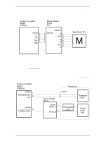
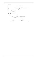
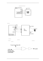
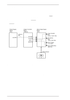
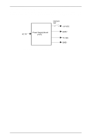
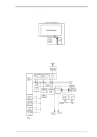
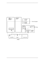
EPL-N1200 Service Manual Figure 2-22 shows the print process. Brush Charging Laser Exposure Development PC Drum Operating Principles Image Transfer Figure 2-22. Print Process Figure 2-23 shows the start print sequence. The printer's engine starts printing when the PRINT signal is received from the video controller board. Print Main Motor On Drum 4.09 0.8 Charge (CH1) [sec.] Laser 074 Exposure (LD) Development (DB) 0.5 0.255 Image 0.26 Transfer (CH1) Paper Take-up Solenoid(SL1) 0.3 0.5 Paper Loading Sensor(PC2): On Figure 2-23. Print Sequence (Start) Figure 2-24 is the end of the print sequence. The printer stops the main motor (M1) from rotating when the paper exit sensor turns off after 1.71 seconds. Drum 0.65 Charge (CH1) Main Motor Off [sec.] 0.735 Laser 0.575 0.12 Exposure (LD) Development (DB) 0.195 Image Transfer (CH1) 0.15 1.56 Paper Take-up Solenoid(SL1) Paper Loading Sensor(PC2): Off Paper Exit Sensor(PC3): Off Figure 2-24. Print Sequence (End) Rev. A 2-15
-
 1
1 -
2
-
3
-
4
-
5
-
6
-
7
-
8
-
9
-
10
-
11
-
12
-
13
-
14
-
15
-
16
-
17
-
18
-
19
-
20
-
21
-
22
-
23
-
24
-
25
-
26
-
27
-
28
-
29
-
30
-
31
-
32
-
33
-
34
-
35
-
36
-
37
-
38
-
39
-
40
-
41
-
42
-
43
-
44
-
45
-
46
-
47
-
48
-
49
-
50
-
51
-
52
-
53
-
54
-
55
-
56
-
57
-
58
-
59
-
60
-
61
-
62
-
63
-
64
-
65
-
66
-
67
-
68
-
 69
69 -
 70
70 -
 71
71 -
 72
72 -
 73
73 -
 74
74 -
 75
75 -
 76
76 -
 77
77 -
 78
78 -
 79
79 -
80
-
81
-
82
-
83
-
84
-
85
-
86
-
87
-
88
-
89
-
90
-
91
-
92
-
93
-
94
-
95
-
96
-
97
-
98
-
99
-
100
-
101
-
102
-
103
-
104
-
105
-
106
-
107
-
108
-
109
-
110
-
111
-
112
-
113
-
114
-
115
-
116
-
117
-
118
-
119
-
120
-
121
-
122
-
123
-
124
-
125
-
126
-
127
-
128
-
129
-
130
-
131
-
132
-
133
-
134
-
135
-
136
-
137
-
138
-
139
-
140
-
141
-
142
-
143
-
144
-
145
-
146
-
147
-
148
-
149
 |
 |
