Epson EPL-N1200 Service Manual - Page 76
VIDEO CONTROLLER OPERATION, C205 MAIN Board Operation, Video Controller
 |
View all Epson EPL-N1200 manuals
Add to My Manuals
Save this manual to your list of manuals |
Page 76 highlights
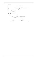
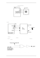
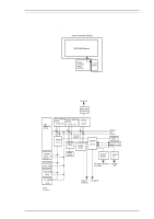
EPL-N1200 Service Manual Operating Principles 2.2 VIDEO CONTROLLER OPERATION The video controller section generates the video signals for the received data. The video controller section is separate in the C205 MAIN board and the control panel. The control panel is connected to the engine controller board (PWB-A), but is controlled by the C205 MAIN board, which sends the signals for the control panel through the engine controller board. Video Controller Section C205 MAIN Board Engine Controller Board (PWB-A) Control Panel Figure 2-26. Video Controller Section 2.2.1 C205 MAIN Board Operation Figure 2-27 shows a block diagram of the C205 MAIN board. The C205 MAIN board contains the video controller, which consists of a MB86930 (SPARKlite, 20 MHz, 32-bit bus) RISC CPU, the standard cells developed for this printer, RAMs, ROMs, and a EEPROM. Parallel-C 74ACT1284 (C29,30,31) CPU MB86930 (IC15) ROM 16M-Bits ROM 16M-Bits (Code) (Font) (IC32, 33) (IC12, 13) E05B27 (IC43) E05A91 (IC 1) I/O Data Address E05B17 (IC16) E05B31 (IC38) E05A93 (IC11) Address Data Control EEPROM (IC5) Control Panel PWB-A Board DRAMs (IC 18, 19, 20, 21) SRAM (IC17) Serial/LT Module Type B I/F RAM SIMM (CN1, CN6) RS-232C, RS-422, or Specific LocalTalk I/F ROM SIMM (CN3) L. L. ROM (IC6) Video I/F Parallel-B (PWB-A) : Option Figure 2-27. C205 Main Board Block Diagram Rev. A 2-17
-
 1
1 -
2
-
3
-
4
-
5
-
6
-
7
-
8
-
9
-
10
-
11
-
12
-
13
-
14
-
15
-
16
-
17
-
18
-
19
-
20
-
21
-
22
-
23
-
24
-
25
-
26
-
27
-
28
-
29
-
30
-
31
-
32
-
33
-
34
-
35
-
36
-
37
-
38
-
39
-
40
-
41
-
42
-
43
-
44
-
45
-
46
-
47
-
48
-
49
-
50
-
51
-
52
-
53
-
54
-
55
-
56
-
57
-
58
-
59
-
60
-
61
-
62
-
63
-
64
-
65
-
66
-
67
-
68
-
69
-
70
-
 71
71 -
 72
72 -
 73
73 -
 74
74 -
 75
75 -
 76
76 -
 77
77 -
 78
78 -
 79
79 -
 80
80 -
 81
81 -
82
-
83
-
84
-
85
-
86
-
87
-
88
-
89
-
90
-
91
-
92
-
93
-
94
-
95
-
96
-
97
-
98
-
99
-
100
-
101
-
102
-
103
-
104
-
105
-
106
-
107
-
108
-
109
-
110
-
111
-
112
-
113
-
114
-
115
-
116
-
117
-
118
-
119
-
120
-
121
-
122
-
123
-
124
-
125
-
126
-
127
-
128
-
129
-
130
-
131
-
132
-
133
-
134
-
135
-
136
-
137
-
138
-
139
-
140
-
141
-
142
-
143
-
144
-
145
-
146
-
147
-
148
-
149
 |
 |
