Epson EPL-N1200 Service Manual - Page 79
MB86930, E05A91, Reset Circuit, Bus Control Circuit
 |
View all Epson EPL-N1200 manuals
Add to My Manuals
Save this manual to your list of manuals |
Page 79 highlights
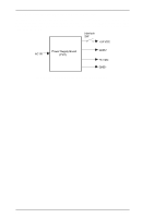
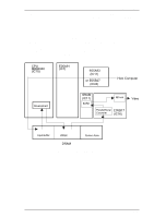
Operating Principles EPL-N1200 Service Manual 2.2.1.1 Reset Circuit The entire system (CPU and external devices) can be initialized if the RESET signal (CPU pin 113) is active simultaneously. This circuit uses an M5193B IC to monitor the supply voltage if the voltage level less than 4.25 V is detected. The reset time is approximately 128 ms. +5V +5V Vcc OUT M51953B (IC2) C RSTIN RSTOUT E05B31 (IC38) RESET Figure 2-29. Reset Circuit 2.2.1.2 Bus Control Circuit The MB86930 CPU outputs the R/W (read/write) signal, AS (address strobe) signal, and the BE0, BE1, BE2, and BE3 signals (byte enables) to the ASIC E05A91. The ASIC E05A91 uses these signals to generate the RD (read strobe) signal, WR (write strobe) signal, and READY signal. CPU MB86930 (IC15) R/W AS BE0-3 READY E05A91 (IC1) Address Data RD WR Bus Bus Figure 2-30. Bus Control Circuit 2-20 Rev. A
-
 1
1 -
2
-
3
-
4
-
5
-
6
-
7
-
8
-
9
-
10
-
11
-
12
-
13
-
14
-
15
-
16
-
17
-
18
-
19
-
20
-
21
-
22
-
23
-
24
-
25
-
26
-
27
-
28
-
29
-
30
-
31
-
32
-
33
-
34
-
35
-
36
-
37
-
38
-
39
-
40
-
41
-
42
-
43
-
44
-
45
-
46
-
47
-
48
-
49
-
50
-
51
-
52
-
53
-
54
-
55
-
56
-
57
-
58
-
59
-
60
-
61
-
62
-
63
-
64
-
65
-
66
-
67
-
68
-
69
-
70
-
71
-
72
-
73
-
 74
74 -
 75
75 -
 76
76 -
 77
77 -
 78
78 -
 79
79 -
 80
80 -
 81
81 -
 82
82 -
 83
83 -
 84
84 -
85
-
86
-
87
-
88
-
89
-
90
-
91
-
92
-
93
-
94
-
95
-
96
-
97
-
98
-
99
-
100
-
101
-
102
-
103
-
104
-
105
-
106
-
107
-
108
-
109
-
110
-
111
-
112
-
113
-
114
-
115
-
116
-
117
-
118
-
119
-
120
-
121
-
122
-
123
-
124
-
125
-
126
-
127
-
128
-
129
-
130
-
131
-
132
-
133
-
134
-
135
-
136
-
137
-
138
-
139
-
140
-
141
-
142
-
143
-
144
-
145
-
146
-
147
-
148
-
149
 |
 |
