Epson EPL-N1200 Service Manual - Page 80
E05A91, DRAM Management
 |
View all Epson EPL-N1200 manuals
Add to My Manuals
Save this manual to your list of manuals |
Page 80 highlights
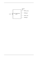
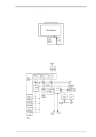
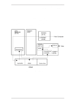
EPL-N1200 Service Manual Operating Principles 2.2.1.3 Interrupt Control The ASIC E05A93 determines the priority level of the interrupt and outputs it to terminals IRL0 IRL3. Then an interrupt is sent to the CPU. When the IRL0-3 value is 1111B, the CPU process is a non-maskable interrupt process. When the IRL0-3 value is 0000B, the CPU process is a standard process. When the IRL0-3 is any other value, the CPU process is a maskable interrupt process. 2.2.1.4 DRAM Management The video controller uses DRAMs for the system RAM and for the V-RAM. In this printer, four standard 512K × 8bit DRAMs are mounted in locations IC18, IC19, IC20, and IC21, providing a total of 2 MB. SIMM sockets number 1 (CN1) and number 2 (CN6) are optional SIMM sockets. These SIMM sockets can use 1, 2, 4, 8, 16, 32 MB SIMM (32-bit bus). The DRAMs (including optional SIMMs) are managed by the ASIC E05A91, which also outputs MA0-10 (memory address), RAS/CAS, and DWE signals. RAS3,4 RAS1,2 RAS0 DWE E05A91 (IC1) CAS0,1,2,3 MA0-10 DRAM (IC18) DRAM (IC19) DRAM (IC20) DRAM (IC21) SIMM Slot 1 (CN1) CPU DATA BUS Figure 2-31. DRAM Management SIMM Slot 2 (CN6) Rev. A 2-21
-
 1
1 -
2
-
3
-
4
-
5
-
6
-
7
-
8
-
9
-
10
-
11
-
12
-
13
-
14
-
15
-
16
-
17
-
18
-
19
-
20
-
21
-
22
-
23
-
24
-
25
-
26
-
27
-
28
-
29
-
30
-
31
-
32
-
33
-
34
-
35
-
36
-
37
-
38
-
39
-
40
-
41
-
42
-
43
-
44
-
45
-
46
-
47
-
48
-
49
-
50
-
51
-
52
-
53
-
54
-
55
-
56
-
57
-
58
-
59
-
60
-
61
-
62
-
63
-
64
-
65
-
66
-
67
-
68
-
69
-
70
-
71
-
72
-
73
-
74
-
 75
75 -
 76
76 -
 77
77 -
 78
78 -
 79
79 -
 80
80 -
 81
81 -
 82
82 -
 83
83 -
 84
84 -
 85
85 -
86
-
87
-
88
-
89
-
90
-
91
-
92
-
93
-
94
-
95
-
96
-
97
-
98
-
99
-
100
-
101
-
102
-
103
-
104
-
105
-
106
-
107
-
108
-
109
-
110
-
111
-
112
-
113
-
114
-
115
-
116
-
117
-
118
-
119
-
120
-
121
-
122
-
123
-
124
-
125
-
126
-
127
-
128
-
129
-
130
-
131
-
132
-
133
-
134
-
135
-
136
-
137
-
138
-
139
-
140
-
141
-
142
-
143
-
144
-
145
-
146
-
147
-
148
-
149
 |
 |
