Epson EPL-N1200 Service Manual - Page 68
Gears and Rollers 1, 1.2.1 Main Motor Functions and Control
 |
View all Epson EPL-N1200 manuals
Add to My Manuals
Save this manual to your list of manuals |
Page 68 highlights
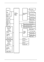
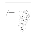
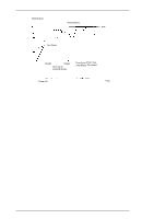
EPL-N1200 Service Manual Operating Principles 2.1.2.1 Main Motor Functions and Control Power from the main motor (M1) drive is used for the P/C (photo conductor) drive, the developing drive, the fusing drive, the standard paper slot feeding drive, and the lower paper cassette (optional) feeding drive. Figures 2-13 and 2-14 show the positions of the gears and rollers. 25 26 6 5 10 18 19 29 28 20 15 14 20 8 7 21 4 13 16 31 30 27 18 12 3 2 1 0 9 11 29 28 31 30 27 0: Main Motor (M1) 4: PC Drum 10: Paper Take-up Roller 11: Transport Roller 13: Upper Fusing Roller 15: Paper Exit Roller 21: Image Transfer Roller Figure 2-13. Gears and Rollers (1) Rev. A 2-9
-
 1
1 -
2
-
3
-
4
-
5
-
6
-
7
-
8
-
9
-
10
-
11
-
12
-
13
-
14
-
15
-
16
-
17
-
18
-
19
-
20
-
21
-
22
-
23
-
24
-
25
-
26
-
27
-
28
-
29
-
30
-
31
-
32
-
33
-
34
-
35
-
36
-
37
-
38
-
39
-
40
-
41
-
42
-
43
-
44
-
45
-
46
-
47
-
48
-
49
-
50
-
51
-
52
-
53
-
54
-
55
-
56
-
57
-
58
-
59
-
60
-
61
-
62
-
 63
63 -
 64
64 -
 65
65 -
 66
66 -
 67
67 -
 68
68 -
 69
69 -
 70
70 -
 71
71 -
 72
72 -
 73
73 -
74
-
75
-
76
-
77
-
78
-
79
-
80
-
81
-
82
-
83
-
84
-
85
-
86
-
87
-
88
-
89
-
90
-
91
-
92
-
93
-
94
-
95
-
96
-
97
-
98
-
99
-
100
-
101
-
102
-
103
-
104
-
105
-
106
-
107
-
108
-
109
-
110
-
111
-
112
-
113
-
114
-
115
-
116
-
117
-
118
-
119
-
120
-
121
-
122
-
123
-
124
-
125
-
126
-
127
-
128
-
129
-
130
-
131
-
132
-
133
-
134
-
135
-
136
-
137
-
138
-
139
-
140
-
141
-
142
-
143
-
144
-
145
-
146
-
147
-
148
-
149
 |
 |

2.1.2.1 Main Motor Functions and Control
Power from the main motor (M1) drive is used for the P/C (photo conductor) drive, the developing
drive, the fusing drive, the standard paper slot feeding drive, and the lower paper cassette (optional)
feeding drive.
Figures 2-13 and 2-14 show the positions of the gears and rollers.
0:
Main Motor (M1)
4:
PC Drum
10: Paper Take-up Roller
11: Transport Roller
13:
Upper Fusing Roller
15: Paper Exit Roller
21:
Image Transfer Roller
Figure 2-13. Gears and Rollers (1)
29
28
27
30
31
20
18
28
29
19
27
30
31
18
10
5
6
11
9
0
1
2
3
12
16
13
15
14
21
8
4
7
25
26
20
EPL-N1200 Service Manual
Operating Principles
Rev. A
2-9