Epson EPL-N1200 Service Manual - Page 81
E05B27, E05A93, Parallel-B Interface Circuit
 |
View all Epson EPL-N1200 manuals
Add to My Manuals
Save this manual to your list of manuals |
Page 81 highlights
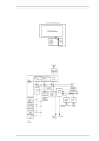
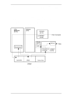
Operating Principles EPL-N1200 Service Manual 2.2.1.5 Parallel-B Interface Circuit Figure 2-32 shows the Parallel-B interface circuit block diagram. Data sent from the host computer is latched within the E05A93 by the STROBE signal. The E05A93 outputs the BUSY signal to stop the host computer from sending additional data. The CPU resets the BUSY signal after reading the data from the E05A93, so that the printer is ready to receive more data from the host computer. DATA STROBE BUSY Latch Latch E05A93 (IC11) Figure 2-32. Parallel-B Interface Circuit 2.2.1.6 Parallel-C Interface Circuit Figure 2-33 shows the Parallel-C interface circuit block diagram. The 74ACT1284 is a bi-directional bus driver IC that used to satisfy the data bus length under the IEEE1284 standard. The E05B27(IC43) is used the Parallel-C interface to support, not only standard parallel interface, but also compatibility mode and bi-directional mode (Nibble and ECP) under the IEEE1284 standard. Data 0-7 BUSY /ACK PE SELECT /ERR /STB /SEL IN /AUTO /INIT 74ACT1284 /DIR /DIR PD 0-7 BUSY /ACK PE SELECT /ERR /STB /SEL IN /AUTO /INIT I/ODB0-7 E05B27 (IC43) DB 0-7 AB 0-4 E05A93 (IC11) Figure 2-33. Parallel-C Interface Circuit 2-22 Rev. A
-
 1
1 -
2
-
3
-
4
-
5
-
6
-
7
-
8
-
9
-
10
-
11
-
12
-
13
-
14
-
15
-
16
-
17
-
18
-
19
-
20
-
21
-
22
-
23
-
24
-
25
-
26
-
27
-
28
-
29
-
30
-
31
-
32
-
33
-
34
-
35
-
36
-
37
-
38
-
39
-
40
-
41
-
42
-
43
-
44
-
45
-
46
-
47
-
48
-
49
-
50
-
51
-
52
-
53
-
54
-
55
-
56
-
57
-
58
-
59
-
60
-
61
-
62
-
63
-
64
-
65
-
66
-
67
-
68
-
69
-
70
-
71
-
72
-
73
-
74
-
75
-
 76
76 -
 77
77 -
 78
78 -
 79
79 -
 80
80 -
 81
81 -
 82
82 -
 83
83 -
 84
84 -
 85
85 -
 86
86 -
87
-
88
-
89
-
90
-
91
-
92
-
93
-
94
-
95
-
96
-
97
-
98
-
99
-
100
-
101
-
102
-
103
-
104
-
105
-
106
-
107
-
108
-
109
-
110
-
111
-
112
-
113
-
114
-
115
-
116
-
117
-
118
-
119
-
120
-
121
-
122
-
123
-
124
-
125
-
126
-
127
-
128
-
129
-
130
-
131
-
132
-
133
-
134
-
135
-
136
-
137
-
138
-
139
-
140
-
141
-
142
-
143
-
144
-
145
-
146
-
147
-
148
-
149
 |
 |
