Epson EPL-N1200 Service Manual - Page 65
Image Transfer, Fusing, 1.1.6 Image Transfer, 1.1.7 Fusing, 1.1.8 Paper Exit
 |
View all Epson EPL-N1200 manuals
Add to My Manuals
Save this manual to your list of manuals |
Page 65 highlights
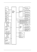
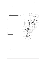
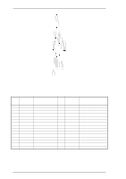
Operating Principles EPL-N1200 Service Manual 2.1.1.6 Image Transfer Image transfer is the process of transferring the toner image created on the PC drum to the paper during the developing process. This printer uses the roller image transfer method, instead of corona image transfer, as the image transfer process. In roller image transfer, there is no generation of ozone as there is with corona discharge. Also, there is no blurring caused by motion in the image transfer, because the image transfer roller is maintained for the pressure bonding of the paper with the PC drum. A reverse bias voltage is applied so that the positive toner is not transferred onto the image transfer roller. (The drum charge bias voltage is used.) Figure 2-8. Image Transfer 2.1.1.7 Fusing Fusing is the process of fixing the toner image transferred during the image transfer process onto the paper. This printer uses the heating roller method for fusing. The heating roller method fixes the toner image with an upper fusing roller that is heated by the heater lamp. The thermistor (TH1) detects the temperature of the upper fusing roller and the value is fed back to the PWB-A board to controls On/Off operation of the heater lamp. If the thermostat (S3) detects 210° C (410° F), inside the terminal, S3 goes open and cut the current off to the heater lamp (H1). Figure 2-9. Fusing 2.1.1.8 Paper Exit The paper on which the toner image has been fused is fed to the face-down tray. 2-6 Rev. A
-
 1
1 -
2
-
3
-
4
-
5
-
6
-
7
-
8
-
9
-
10
-
11
-
12
-
13
-
14
-
15
-
16
-
17
-
18
-
19
-
20
-
21
-
22
-
23
-
24
-
25
-
26
-
27
-
28
-
29
-
30
-
31
-
32
-
33
-
34
-
35
-
36
-
37
-
38
-
39
-
40
-
41
-
42
-
43
-
44
-
45
-
46
-
47
-
48
-
49
-
50
-
51
-
52
-
53
-
54
-
55
-
56
-
57
-
58
-
59
-
 60
60 -
 61
61 -
 62
62 -
 63
63 -
 64
64 -
 65
65 -
 66
66 -
 67
67 -
 68
68 -
 69
69 -
 70
70 -
71
-
72
-
73
-
74
-
75
-
76
-
77
-
78
-
79
-
80
-
81
-
82
-
83
-
84
-
85
-
86
-
87
-
88
-
89
-
90
-
91
-
92
-
93
-
94
-
95
-
96
-
97
-
98
-
99
-
100
-
101
-
102
-
103
-
104
-
105
-
106
-
107
-
108
-
109
-
110
-
111
-
112
-
113
-
114
-
115
-
116
-
117
-
118
-
119
-
120
-
121
-
122
-
123
-
124
-
125
-
126
-
127
-
128
-
129
-
130
-
131
-
132
-
133
-
134
-
135
-
136
-
137
-
138
-
139
-
140
-
141
-
142
-
143
-
144
-
145
-
146
-
147
-
148
-
149
 |
 |
