Epson EPL-N1200 Service Manual - Page 70
Main Motor Drive Circuit, Fuser Control Circuit, Main Motor M1, Power Supply, Board
 |
View all Epson EPL-N1200 manuals
Add to My Manuals
Save this manual to your list of manuals |
Page 70 highlights
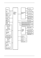
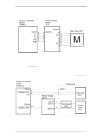
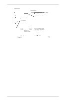
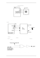
EPL-N1200 Service Manual Operating Principles Figure 2-15 shows the main motor drive circuit. The main motor (M1) is a four-phase stepping motor. This motor is controlled by the CPU (IC1) on the engine controller board (PWB-A). The power supply board (PU1) has a stepping motor driver IC. This IC drives the main motor (M1) with a constant current. Engine Controller Board PWB-A Power Supply Board PU1 CN10A A 2 3 B4 TdA 5 TdB CN5PU1 5 CN3PU1 4 3 2 B1 24V 2 3 B4 A5 24V 6 A Main Motor M1 M Figure 2-15. Main Motor Drive Circuit 2.1.2.2 Fuser Control The fuser is heated by the heater lamp, which is powered by AC voltage. When the power supply board receives a FUSER LAMP signal from the engine controller board (PWB-A), the power supply board (PU1) supplies the AC voltage to the heater lamp. This AC voltage is cut by the interlock switch when the top cover opens. The fuser temperature is detected by the thermistor. Based on the TH1 signal from the thermistor, the engine controller board (PWB-A) controls the fusing temperature using the FUSER LAMP signal. Engine Controller Board (PWB-A) Fusing Unit CN2A 1 THERMISTOR 2 +5V Power Supply (PU1) 1 CN1T 2 Thermistor (TH1) CN10A 6 FUSER LAMP CN1H 1 HEAT-L 2 HEAT-N Thermostat (S3) Heater Lamp (H1) Figure 2-16. Fuser Control Circuit Rev. A 2-11
-
 1
1 -
2
-
3
-
4
-
5
-
6
-
7
-
8
-
9
-
10
-
11
-
12
-
13
-
14
-
15
-
16
-
17
-
18
-
19
-
20
-
21
-
22
-
23
-
24
-
25
-
26
-
27
-
28
-
29
-
30
-
31
-
32
-
33
-
34
-
35
-
36
-
37
-
38
-
39
-
40
-
41
-
42
-
43
-
44
-
45
-
46
-
47
-
48
-
49
-
50
-
51
-
52
-
53
-
54
-
55
-
56
-
57
-
58
-
59
-
60
-
61
-
62
-
63
-
64
-
 65
65 -
 66
66 -
 67
67 -
 68
68 -
 69
69 -
 70
70 -
 71
71 -
 72
72 -
 73
73 -
 74
74 -
 75
75 -
76
-
77
-
78
-
79
-
80
-
81
-
82
-
83
-
84
-
85
-
86
-
87
-
88
-
89
-
90
-
91
-
92
-
93
-
94
-
95
-
96
-
97
-
98
-
99
-
100
-
101
-
102
-
103
-
104
-
105
-
106
-
107
-
108
-
109
-
110
-
111
-
112
-
113
-
114
-
115
-
116
-
117
-
118
-
119
-
120
-
121
-
122
-
123
-
124
-
125
-
126
-
127
-
128
-
129
-
130
-
131
-
132
-
133
-
134
-
135
-
136
-
137
-
138
-
139
-
140
-
141
-
142
-
143
-
144
-
145
-
146
-
147
-
148
-
149
 |
 |
