Epson EPL-N1200 Service Manual - Page 67
Engine Control, Engine Controller Connecting Diagram, PWB-B
 |
View all Epson EPL-N1200 manuals
Add to My Manuals
Save this manual to your list of manuals |
Page 67 highlights
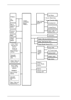
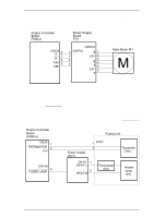
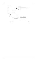
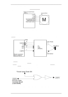
Operating Principles EPL-N1200 Service Manual 2.1.2 Engine Control This section describes engine control, the power supply board, and the high-voltage supply board. The engine is controlled by the engine controller board (PWB-A board). Figure 2-12 shows an engine controller connecting diagram. PWB-D LD SOS Mirror Scanner Motor Control Panel Main Controller Board C205 MAIN Lower Paper Cassette #1 (option) PWB-B Paper Empty Sensor Cassette Detecting SW Paper Take Up Solenoid SL2 Lower Paper Cassette #2 (option) PWB-B Paper Empty Sensor Cassette Detecting SW Paper Take Up Solenoid SL2 Engine Controller Board PWB-A Fan Motor High Voltage Supply B HV-1 Doctor Blade Bias Image Transfer Roller Development Charge Brush Paper Take Up Sensor PC2 Thermistor Paper Take Up Solenoid SL1 Paper Exit Sensor PC3 Paper Empty Sensor PC1 Power Supply Board PU1 Power SW AC Power Input Interlock SW Heater Lamp Main Motor PWB-G Toner Empty Sensor PWB-S Transfer Current Change SW. Figure 2-12. Engine Controller Connecting Diagram 2-8 Rev. A
-
 1
1 -
2
-
3
-
4
-
5
-
6
-
7
-
8
-
9
-
10
-
11
-
12
-
13
-
14
-
15
-
16
-
17
-
18
-
19
-
20
-
21
-
22
-
23
-
24
-
25
-
26
-
27
-
28
-
29
-
30
-
31
-
32
-
33
-
34
-
35
-
36
-
37
-
38
-
39
-
40
-
41
-
42
-
43
-
44
-
45
-
46
-
47
-
48
-
49
-
50
-
51
-
52
-
53
-
54
-
55
-
56
-
57
-
58
-
59
-
60
-
61
-
 62
62 -
 63
63 -
 64
64 -
 65
65 -
 66
66 -
 67
67 -
 68
68 -
 69
69 -
 70
70 -
 71
71 -
 72
72 -
73
-
74
-
75
-
76
-
77
-
78
-
79
-
80
-
81
-
82
-
83
-
84
-
85
-
86
-
87
-
88
-
89
-
90
-
91
-
92
-
93
-
94
-
95
-
96
-
97
-
98
-
99
-
100
-
101
-
102
-
103
-
104
-
105
-
106
-
107
-
108
-
109
-
110
-
111
-
112
-
113
-
114
-
115
-
116
-
117
-
118
-
119
-
120
-
121
-
122
-
123
-
124
-
125
-
126
-
127
-
128
-
129
-
130
-
131
-
132
-
133
-
134
-
135
-
136
-
137
-
138
-
139
-
140
-
141
-
142
-
143
-
144
-
145
-
146
-
147
-
148
-
149
 |
 |
