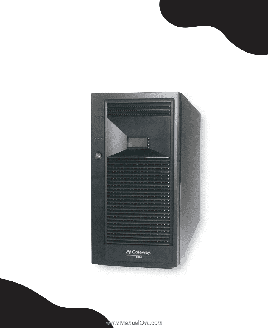
Gateway E-9510T Gateway 9510 Server User Guide
Gateway E-9510T Manual
 |
View all Gateway E-9510T manuals
Add to My Manuals
Save this manual to your list of manuals |
Gateway E-9510T manual content summary:
- Gateway E-9510T | Gateway 9510 Server User Guide - Page 1
Gateway 9510 Server User Guide - Gateway E-9510T | Gateway 9510 Server User Guide - Page 2
side 7 Right side 8 Getting Help 9 System Companion CD 9 Gateway Web site 9 2 Setting Up Your Server 11 Setting up the hardware 12 Converting to a rackmount server 12 Protecting from power source problems 18 Starting your server 19 Understanding the power-on self-test 20 Turning off your - Gateway E-9510T | Gateway 9510 Server User Guide - Page 3
activation key and dedicated RAID memory 79 Replacing a power supply module 81 Replacing a power distribution module 83 Replacing the BIOS Setup Utility 99 Opening the BIOS Setup utility 100 Updating the BIOS 101 Rolling BIOS 101 Recovering the BIOS 102 Resetting the BIOS 105 Resetting BIOS - Gateway E-9510T | Gateway 9510 Server User Guide - Page 4
150 Additional beep codes provided by optional Intel Management Modules 152 LED information 152 Diagnostic LEDs 154 BIOS 161 CD or DVD drive 161 Diskette drive 161 Expansion cards 162 Hard drive 162 Internet 164 Keyboard 164 Memory 164 Modem (telephone dial-up 164 Monitor 166 Power 167 - Gateway E-9510T | Gateway 9510 Server User Guide - Page 5
B BIOS Settings 183 C Safety, Regulatory, and Legal Information 199 Index 209 iv www.gateway.com - Gateway E-9510T | Gateway 9510 Server User Guide - Page 6
Chapter 1 Checking Out Your Gateway Server • Locating drives, ports, jacks, and controls • Locating system board components • Getting help 1 - Gateway E-9510T | Gateway 9510 Server User Guide - Page 7
Chapter 1: Checking Out Your Gateway Server Front Control panel CD or DVD drive Cover release button Additional drive bay Local control panel (LCP) (optional) USB ports Serial port B Key lock Cover release latch 2 www.gateway.com - Gateway E-9510T | Gateway 9510 Server User Guide - Page 8
Control panel ID button Reset button NIC 1 activity LED ID LED NIC 2 activity LED Reserved for future use Power button Hard drive activity LED Power/sleep LED Status LED NMI button Front www.gateway.com 3 - Gateway E-9510T | Gateway 9510 Server User Guide - Page 9
Chapter 1: Checking Out Your Gateway Server Hard drive bays Optional hot-swap drive bays (4) Hot-swap drive bays (6) 4 www.gateway.com - Gateway E-9510T | Gateway 9510 Server User Guide - Page 10
Diagnostic LEDS NIC 2 (RJ-45) NIC 1 (RJ-45) Status LED ID LED Back Power supply module Power supply module latch Power supply module Power supply module latch Power connector Power supply LEDs Kensington lock slot PCI slots (shown with EMI shields) Card retention levers www.gateway.com 5 - Gateway E-9510T | Gateway 9510 Server User Guide - Page 11
Chapter 1: Checking Out Your Gateway Server Interior Power supply module Power distribution module Processor air duct 5.25-inch drive bay Front panel board Card retention clips Cable clip PCI air duct Hot-swap Hot-swap fans - Gateway E-9510T | Gateway 9510 Server User Guide - Page 12
Left side Memory banks USB 1, 2, and 3 connectors Mouse/keyboard connectors Serial/video connectors Auxiliary signal Main power connector connector System board +12V CPU power connector Diagnostic LEDS HDD LED connector Front panel connector Chassis intrusion connector www.gateway.com 7 - Gateway E-9510T | Gateway 9510 Server User Guide - Page 13
Chapter 1: Checking Out Your Gateway Server Right side CPU 2 CPU 1 fault fault LED LED CPU 1 CPU 2 socket socket Intel® Management Module (IMM) HSBP A connector SCSI channel B connector IPMB connector CMOS Front panel control LED battery connector SCSI channel A connector 8 www.gateway.com - Gateway E-9510T | Gateway 9510 Server User Guide - Page 14
Using Your System Companion CD. Gateway Web site Gateway provides a variety of information on its Web site to help you use your server. Visit the Gateway Web site at support.gateway.com for: ■ Technical documentation and product guides ■ Technical tips and support ■ Updated hardware drivers ■ Order - Gateway E-9510T | Gateway 9510 Server User Guide - Page 15
Chapter 1: Checking Out Your Gateway Server 10 www.gateway.com - Gateway E-9510T | Gateway 9510 Server User Guide - Page 16
Chapter 2 Setting Up Your Server • Using your server safely • Starting and turning off your server • Restarting (rebooting) your server • Setting up the operating system 11 - Gateway E-9510T | Gateway 9510 Server User Guide - Page 17
and air circulation. ■ Use the instructions on your server's setup poster to set up your hardware. ■ Use an uninterruptible power supply (UPS) with surge protection for protection from power outages and power spikes. Warning Your server comes with a 3-wire AC power cords fitted with the correct - Gateway E-9510T | Gateway 9510 Server User Guide - Page 18
it to the rack is a two-person job. If needed, use an appropriate lifting device. A fully loaded Gateway 9510 server weighs about 80 lbs (36.2 kg). To convert your server to rackmount configuration: 1 Follow the instructions in "Preventing static electricity discharge" on page 41. 2 Follow the - Gateway E-9510T | Gateway 9510 Server User Guide - Page 19
to pop the center plastic rivet free from each foot. c Remove the feet (and leave the server on its side). 7 Remove the diskette, CD, and DVD drives and filler panels from the server by following the instructions in "Installing or replacing a fixed, removable-media drive" on page 54. 8 Re-orient the - Gateway E-9510T | Gateway 9510 Server User Guide - Page 20
opening and tightening the captive thumbscrew. 9 Reinstall the diskette, CD, or DVD drives and filler panels in the horizontal orientation and reconnect the data and power cables to the drives. www.gateway.com 15 - Gateway E-9510T | Gateway 9510 Server User Guide - Page 21
the rack conversion kit) on the chassis intrusion switch header on the front panel control board. 12 Install the handles on each side of the server with the three screws provided in the kit for that purpose. Handles should face outwards. 16 www - Gateway E-9510T | Gateway 9510 Server User Guide - Page 22
label (readable from the horizontal) over the LEDs and buttons on the bezel. 17 Reinstall the cover by following the instructions in "Closing the server case" on page 52. 18 Install the rackmount rail kit by following the instructions in the manual that accompanied the kit. www.gateway.com 17 - Gateway E-9510T | Gateway 9510 Server User Guide - Page 23
Protecting from power source problems Line conditioners, and uninterruptible power supplies can help protect your server against power source problems. Line conditioners A line conditioner protects your server from the small fluctuations in voltage from an electrical supply. Most servers can handle - Gateway E-9510T | Gateway 9510 Server User Guide - Page 24
are turned off and the power cords are unplugged. To start the server: 1 Press the power button. Power button Power/sleep LED When the power/sleep LED is... Green Off Slowly blinking It means... The server is turned on. The server is turned off. Low power state (S1 - S3) www.gateway.com 19 - Gateway E-9510T | Gateway 9510 Server User Guide - Page 25
power-on self-test (POST) routine checks the server memory and components. If POST finds any problems, the server displays error messages. Write down any error messages that you see, then see "Error messages" on page 147 and "Beep codes" on page 150 for troubleshooting information. 20 www.gateway - Gateway E-9510T | Gateway 9510 Server User Guide - Page 26
's documentation or online help for instructions on shutting down the operating system. Whenever possible, you should use the operating system's shut down procedure instead of pressing the power button. 2 If your server did not turn off automatically, press the power button. If nothing happens when - Gateway E-9510T | Gateway 9510 Server User Guide - Page 27
system's documentation for instructions on completing the installation or configuring advanced settings for your specific network. If you are installing an operating system because it was not already installed by Gateway, see the appropriate installation guide for instructions. 22 www.gateway.com - Gateway E-9510T | Gateway 9510 Server User Guide - Page 28
a tasking change, a change in security requirements, or the addition of new resources to your server. General hardware settings, as well as the onboard LSI RAID solution, can be changed by using the BIOS Setup utility, and advanced RAID settings for the Intel ROMB RAID solution can be changed by - Gateway E-9510T | Gateway 9510 Server User Guide - Page 29
Chapter 2: Setting Up Your Server 24 www.gateway.com - Gateway E-9510T | Gateway 9510 Server User Guide - Page 30
Chapter 3 Maintaining Your Server • Caring for your server • Recording the BIOS configuration • Managing your server and network 25 - Gateway E-9510T | Gateway 9510 Server User Guide - Page 31
. Your server cleaning kit could include: ■ A soft, lint-free cloth ■ Glass cleaner ■ An aerosol can of air with a narrow, straw-like extension ■ Isopropyl alcohol ■ Cotton swabs ■ A tape drive cleaning cartridge (if a tape drive is installed) ■ A CD or DVD drive cleaning kit 26 www.gateway.com - Gateway E-9510T | Gateway 9510 Server User Guide - Page 32
your server. To avoid possible injury from electrical shock, unplug the power cords and all other cables connected to the server. ■ Use a damp, lint-free cloth to clean your server and other parts of your server system. the tape from the drive whenever the drive is not in use. www.gateway.com 27 - Gateway E-9510T | Gateway 9510 Server User Guide - Page 33
prepare for system recovery, you should record your BIOS configuration after you have your server set up and working. To record your BIOS configuration: 1 Print the appendix for BIOS Settings in this guide. 2 Restart your server, then press F2 when the Gateway logo screen appears during startup. The - Gateway E-9510T | Gateway 9510 Server User Guide - Page 34
the Gateway Server Manager CD 9510 server and lets you configure the server, monitor system status, and control the server power state of the server ■ Query the BMC for field replaceable units (FRUs) ■ Read BMC sensors ■ Retrieve BIOS POST progress codes ■ Issue IPMI commands to the BMC ■ Obtain BIOS - Gateway E-9510T | Gateway 9510 Server User Guide - Page 35
following table shows the LCP menu options: Menu Configure the server Options Network (LAN channel 1 to 3) ■ IP address (BMC) ■ Netmask ■ Gateway address ■ Enable LAN channel Inventory ■ CPUs ■ DIMMs ■ Drives ■ Power supplies ■ System fans Description Configure TCO NIC View system inventory 30 - Gateway E-9510T | Gateway 9510 Server User Guide - Page 36
codes View POST progress codes Server health (drill down to subsystem(s) View the health of the system at fault) System event log View the system event log CPU sensors (CPU 1 to n) ■ Presence ■ Over temperature ■ On/off line View CPU related status Chassis status Intrusion status Power supply - Gateway E-9510T | Gateway 9510 Server User Guide - Page 37
Power control ■ Power on ■ Power off (graceful or hard) Reset IPMI control ■ Power on ■ Power off (graceful or hard) IPMI command screen ■ Issue an IPMI command (text or hex) Set up the server order Power control Control the power state by creating button Power control IPMI control Send the chipset a power - Gateway E-9510T | Gateway 9510 Server User Guide - Page 38
password to access the BIOS Setup utility. For information about resetting BIOS passwords, see "Resetting BIOS passwords" on page 107. To set the BIOS security passwords: 1 Restart your server, then press F2 when the Gateway logo screen appears during startup. The BIOS Setup utility opens. 2 Select - Gateway E-9510T | Gateway 9510 Server User Guide - Page 39
not need to be turned on, but it does need to be plugged in. Important If your server has an Intel IMM module installed, the system ID LED will turn on or off when the System ID ID indicator LED System ID indicator LED 2 To turn off the indicator, press the System ID button. 34 www.gateway.com - Gateway E-9510T | Gateway 9510 Server User Guide - Page 40
-on-key device or DOS-bootable CD. 2 Download the BMC update file from support.gateway.com. 3 Follow the instructions included with the update file. 4 Turn off the server, then disconnect the power cord and wait for the Standby power LED to turn off. To update the BMC firmware with Boot Block and - Gateway E-9510T | Gateway 9510 Server User Guide - Page 41
update 5 Move the shorting block from pins 1-2 to pins 2-3 on the Force Update jumper (J2B1) on the IMM module. 6 Follow the instructions in "Installing the air ducts" on page 47. 7 Follow the instructions in "Closing the server case" on page 52, then reconnect the power cord. 36 www.gateway.com - Gateway E-9510T | Gateway 9510 Server User Guide - Page 42
BMC. This includes adding a redundant power supply module, adding redundant hot-swap fans, or adding an Intel Management Module (IMM). The FRU/SDR must also be updated whenever you update the BIOS. Each time you update the FRU/SDR, we recommend that you check support.gateway.com for the most current - Gateway E-9510T | Gateway 9510 Server User Guide - Page 43
installed additional hardware, for example, a redundant power supply or system fans, or additional memory. 5 When you are asked if you server. Using your System Companion CD You can use your System Companion CD to: ■ Install hardware drivers ■ Install programs ■ View server documentation Instructions - Gateway E-9510T | Gateway 9510 Server User Guide - Page 44
Opening and closing the server case • Installing and replacing major components You must open your server case to install components. If you are not comfortable with these procedures, get help from a more experienced computer user or computer service technician, or contact Gateway Customer Care. 39 - Gateway E-9510T | Gateway 9510 Server User Guide - Page 45
) ■ Has a stable surface on which to set your server ■ Has enough room to place all of your server parts ■ Is near a grounded outlet so you can test your server after installation ■ Is near a telephone (in case you need help from Gateway Customer Care). The telephone must be directly connected to - Gateway E-9510T | Gateway 9510 Server User Guide - Page 46
part of the server. You can also touch a bare metal surface on the back of the server with your finger. Warning To prevent risk of electric shock, do not insert any object into the vent holes of the power supply Never slide expansion cards or components over any surface. www.gateway.com 41 - Gateway E-9510T | Gateway 9510 Server User Guide - Page 47
before you turn on the server. Operating the server without the cover in place can damage server components. To open the server case: 1 Follow the instructions in "Preventing static electricity discharge" on page 41. 2 Turn off the server, then unplug the power cords and all other cables connected - Gateway E-9510T | Gateway 9510 Server User Guide - Page 48
Opening the server case 5 Press the latch, then slide the side panel toward the back of the case about ½ inch. 6 Lift the panel away from the server and place it out of the way. www.gateway.com 43 - Gateway E-9510T | Gateway 9510 Server User Guide - Page 49
Chapter 4: Installing Components Removing the bezel assembly To remove the bezel assembly: 1 Follow the instructions in "Opening the server case" on page 42. 2 Unlock the bezel assembly. Release tab Lock Release tab 44 www.gateway.com - Gateway E-9510T | Gateway 9510 Server User Guide - Page 50
the bezel assembly does not immediately disengage from the chassis, tap the left side of the assembly lightly to help disengage the retention hooks. www.gateway.com 45 - Gateway E-9510T | Gateway 9510 Server User Guide - Page 51
discharge" on page 41. 2 Follow the instructions in "Opening the server case" on page 42. 3 Press the latch and remove the PCI air duct from the chassis 4 Press the latch and remove the processor air duct from the chassis. Processor air duct Air duct release buttons PCI air duct 46 www.gateway.com - Gateway E-9510T | Gateway 9510 Server User Guide - Page 52
. Installing the air ducts If you have installed a second processor into your server, remove the plastic air baffle from the inside of the of the processor air duct. Caution If you have installed a second processor in your server and do not remove the plastic air baffle in the processor air duct - Gateway E-9510T | Gateway 9510 Server User Guide - Page 53
Chapter 4: Installing Components 2 Press the PCI air duct into place until the latch clicks. Important The PCI air duct interlocks with the processor air duct in two places before latching into place. 48 www.gateway.com - Gateway E-9510T | Gateway 9510 Server User Guide - Page 54
assembly. If you have installed any new drives in the 5.25" drive bays, make sure to remove the corresponding filler panels in the bezel. www.gateway.com 49 - Gateway E-9510T | Gateway 9510 Server User Guide - Page 55
the chassis until the two plastic tabs on the left side of the bezel assembly snap into place. 5 Relock the bezel, if required. 50 www.gateway.com - Gateway E-9510T | Gateway 9510 Server User Guide - Page 56
1 Complete the installation of the rackmount conversion kit by following the instructions in "To convert your server to rackmount configuration:" on page 13. 2 Engage the two tabs snapping it into place on the front of the server, then use the lock on the right side of the bezel to secure it. www - Gateway E-9510T | Gateway 9510 Server User Guide - Page 57
Chapter 4: Installing Components Closing the server case To close the server case: 1 For more stability, place the server on its side. 2 Make sure that all of the internal case until the latch engages. 4 Set the case upright. 5 Reconnect the power cords and all other cables. 52 www.gateway.com - Gateway E-9510T | Gateway 9510 Server User Guide - Page 58
drive (included with the accessories and not installed in the server). Your server also has two additional 5.25-inch drive bays (if your server is equipped with the LCP panel, only one additional 5.25 on configuring the drive, setting drive jumpers, and attaching cables. www.gateway.com 53 - Gateway E-9510T | Gateway 9510 Server User Guide - Page 59
, CD, DVD, or tape drive. To install a 5.25-inch drive: 1 Follow the instructions in "Preventing static electricity discharge" on page 41. 2 Follow the instructions in "Opening the server case" on page 42. 3 Follow the instructions in "Removing the bezel assembly" on page 44. 4 If you are replacing - Gateway E-9510T | Gateway 9510 Server User Guide - Page 60
's cables from the back of the drive. 9 Press the old drive's release latches against the drive, then pull the drive out of the bay. www.gateway.com 55 - Gateway E-9510T | Gateway 9510 Server User Guide - Page 61
drives To route power and data cables to fixed drives: 1 Follow the instructions in "Preventing static electricity discharge" on page 41. 2 Follow the instructions in "Opening the server case" on page 42. 3 Follow the instructions in "Removing the bezel assembly" on page 44. 56 www.gateway.com - Gateway E-9510T | Gateway 9510 Server User Guide - Page 62
on the cables), to the server board. ■ Routing the longest power cables (P8, P9, P10, and P11) to the six-drive bay. ■ Routing the P6 and P7 power cables to the four-drive bay. ■ Routing the SATA drive power cables to whichever bay is using SATA fixed drives (if necessary). www.gateway.com 57 - Gateway E-9510T | Gateway 9510 Server User Guide - Page 63
bottom of the drive cages. 7 Connect the data cables to the appropriate connector on the system board, then to the corresponding fixed drives. 58 www.gateway.com - Gateway E-9510T | Gateway 9510 Server User Guide - Page 64
or replace hard drives in a hot-swap bay (either SATA or SCSI). Your server supports as many as six SATA or SCSI 1-inch high, 3.5-inch hot-swap hard drive (SCSI hot-swap drives only). Install the topmost drives first. Gateway tests and verifies the operation and compatibility of the drives it sells. - Gateway E-9510T | Gateway 9510 Server User Guide - Page 65
determine which drive has failed. See the system label inside your server for information on identifying the SATA connector and the corresponding drive. software and utilities installed on the server to stop all activity on the failed drive. Instructions for using the software are provided by - Gateway E-9510T | Gateway 9510 Server User Guide - Page 66
Installing drives 3 Pull the drive tray lever down (away from the server), then pull the assembly straight out of the server. 4 If you are replacing a hard drive, remove the four screws that secure the hard drive to the drive tray, then remove the drive from the - Gateway E-9510T | Gateway 9510 Server User Guide - Page 67
holes in the side of the drive tray, then secure the drive to the tray with the four screws you removed in Step 4. 62 www.gateway.com - Gateway E-9510T | Gateway 9510 Server User Guide - Page 68
Installing drives 6 Make sure that the tray's release lever is open, then slide the new drive into the empty hot-swap bay. 7 Close the drive's release lever by rotating the lever upwards to latch the drive carrier into position. 8 Close and relock the bezel door (if required). www.gateway.com 63 - Gateway E-9510T | Gateway 9510 Server User Guide - Page 69
local control panel: 1 Follow the instructions in "Preventing static electricity discharge" on page 41. 2 Follow the instructions in "Opening the server case" on page 42. 3 Follow the instructions in "Removing the bezel assembly" firmly into the dimples on each side of the tray. 64 www.gateway.com - Gateway E-9510T | Gateway 9510 Server User Guide - Page 70
end of the cable to the IPMB header on the system board. See "System board" on page 7 for the location of the header. 9 Follow the instructions on "Installing the bezel assembly" on page 49. 10 Follow the instructions in "Closing the server case" on page 52. www.gateway.com 65 - Gateway E-9510T | Gateway 9510 Server User Guide - Page 71
4: Installing Components Installing memory When you upgrade your server memory, make sure that you install the correct type of memory in your server. Your server supports from 256 MB to 16 GB total memory. Supported DIMM sizes include 256 MB, 512 MB, 1 GB, and 2 GB. Caution Memory modules must be - Gateway E-9510T | Gateway 9510 Server User Guide - Page 72
server case" on page 52. 8 Restart your server and open the BIOS Setup utility. Verify the System Memory listed in the Main menu. When you exit the BIOS Setup utility, make sure that the operating system loads completely. 9 Follow the instructions in "Updating the FRU/SDR" on page 37. www.gateway - Gateway E-9510T | Gateway 9510 Server User Guide - Page 73
to the spare DIMM in that channel. When all of the data is copied, the primary DIMM is automatically removed from service. Since one DIMM per channel is always maintained as a spare, only 75% of the installed memory is usable. Memory online sparing is configured in the BIOS. 68 www.gateway.com - Gateway E-9510T | Gateway 9510 Server User Guide - Page 74
PCI hot-plug capability. Do not attempt to install or remove a PCI card without turning off your server and disconnecting it from the AC power source. PCI slot 1 2 3 4 5 6 Description PCI-X - Runs at 64-bit /133MHz (do not attempt to install a PCI card in this slot) PCI slot 1 www.gateway.com 69 - Gateway E-9510T | Gateway 9510 Server User Guide - Page 75
Components To replace, add, or reseat a PCI expansion card: 1 Follow the instructions in "Preventing static electricity discharge" on page 41. 2 Follow the instructions in "Opening the server case" on page 42. 3 Follow the instructions in "Removing the air ducts" on page 46. 4 If you are replacing - Gateway E-9510T | Gateway 9510 Server User Guide - Page 76
you can slightly rock the card end-to-end, but do not bend the card sideways. Caution Do not touch the contacts on the bottom part of the expansion card. Touching the contacts can cause electrostatic damage to the card. 8 Press the new card into the expansion slot. To help insert - Gateway E-9510T | Gateway 9510 Server User Guide - Page 77
more information, see the instructions in the card's documentation. 12 Follow the instructions in "Installing the air ducts" on page 47. 13 Follow the instructions in "Closing the server case" on page 52. 14 See the card's documentation for software installation instructions. 72 www.gateway.com - Gateway E-9510T | Gateway 9510 Server User Guide - Page 78
. For more information, see "Updating the BIOS" on page 101. 2 Follow the instructions in "Preventing static electricity discharge" on page 41. 3 Follow the instructions in "Opening the server case" on page 42. 4 Follow the instructions in "Removing the air ducts" on page 46. www.gateway.com 73 - Gateway E-9510T | Gateway 9510 Server User Guide - Page 79
locking lever, push it slightly away from the processor, then rotate the lever a full 135° to release the processor. 8 Remove the old processor. 74 www.gateway.com - Gateway E-9510T | Gateway 9510 Server User Guide - Page 80
the same speed. Otherwise, applications that detect processor speed could cause problems. If only one processor is installed, it must be installed in the instructions in "Installing the air ducts" on page 47. 14 Follow the instructions in "Closing the server case" on page 52. www.gateway.com 75 - Gateway E-9510T | Gateway 9510 Server User Guide - Page 81
Management Module (IMM): 1 Uninstall the Gateway Server Manager (GSM) software from your server. 2 Follow the instructions in "Preventing static electricity discharge" on page 41. 3 Follow the instructions in "Opening the server case" on page 42. 4 Follow the instructions in "Removing the air ducts - Gateway E-9510T | Gateway 9510 Server User Guide - Page 82
. Snap lock end goes into system board. 6 Find the IMM connector on the lower front portion of the system board. Standoff hole IMM connector www.gateway.com 77 - Gateway E-9510T | Gateway 9510 Server User Guide - Page 83
" on page 35. 9 Update the FRU/SDR by following the instructions in "Updating the FRU/SDR" on page 37). 10 Reinstall the GSM software (from a CD which accompanied your server). When you subsequently reboot your server, the GSM software will take over management of the server. 78 www.gateway.com - Gateway E-9510T | Gateway 9510 Server User Guide - Page 84
IOP ROMB option in system BIOS will be grayed out. server, the system board also supports the Intel Portable Cache Module accessory, used in place of the RAID DIMM, which provides up to 72 hours of battery back-up. To install the RAID activation key and RAID memory: 1 Follow the instructions - Gateway E-9510T | Gateway 9510 Server User Guide - Page 85
) by following the instructions in "Installing PCI expansion cards" on page 69. 10 Follow the instructions in "Installing the air ducts" on page 47. 11 Follow the instructions in "Closing the server case" on page 52. 12 Configure the BIOS settings to enable the ROMB option. 80 www.gateway.com - Gateway E-9510T | Gateway 9510 Server User Guide - Page 86
, see "Updating the FRU/SDR" on page 37. Warning The power supply modules in this server contain no user-serviceable parts. Only a qualified computer technician should service the power supply modules. Your server comes with 3-wire AC power cords fitted with the correct plug style for your region - Gateway E-9510T | Gateway 9510 Server User Guide - Page 87
the server. 5 Slide the new power supply module into the power supply bay until the green latch snaps into place. 6 Replace the shipping screw (if necessary). 7 Plug the power cord into the new power supply module. The new power supply module is ready if the left (green) LED is on. 82 www.gateway - Gateway E-9510T | Gateway 9510 Server User Guide - Page 88
discharge" on page 41. 2 Follow the instructions in "Opening the server case" on page 42. 3 Remove the power supply module (remove both if two are installed) by following the instructions in "Replacing a power supply module" on page 81. 4 Follow the instructions in "Removing the air ducts" on page - Gateway E-9510T | Gateway 9510 Server User Guide - Page 89
on the mounting standoffs and secure with the thumbscrew you previously loosened. 12 Reinstall the center divider into the power supply cage by engaging the mounting tabs into the chassis slots. 13 Reinstall the screw securing the center divider into the power supply cage. 84 www.gateway.com - Gateway E-9510T | Gateway 9510 Server User Guide - Page 90
instructions in "Installing the air ducts" on page 47. 16 Reinstall the power supply module(s) by following the instructions in "Replacing a power supply module" on page 81. 17 Follow the instructions in "Closing the server case" on page 52. 18 Connect power to the server and restart. www.gateway - Gateway E-9510T | Gateway 9510 Server User Guide - Page 91
hot-swap backplane: 1 Follow the instructions in "Preventing static electricity discharge" on page 41. 2 Follow the instructions in "Opening the server case" on page 42. 3 Follow the instructions in "Removing the bezel assembly" latch for the hot-swap cage you are removing. 86 www.gateway.com - Gateway E-9510T | Gateway 9510 Server User Guide - Page 92
Replacing the hot-swap backplane 7 Slide the hot-swap cage out about two inches from the case. 8 From inside the case, remove the power, data, and manageability cables from the backplane. 9 Remove the hot-swap cage completely from the server. www.gateway.com 87 - Gateway E-9510T | Gateway 9510 Server User Guide - Page 93
the backplane to the drive cage. 14 Slide the hot-swap cage part-way into the hot-swap bay. Make sure that the side of the cage marked "Top" is oriented toward the top of the server case. 15 Connect the power, data, and manageability cables to the backplane. 16 Slide the hot - Gateway E-9510T | Gateway 9510 Server User Guide - Page 94
Replacing the hot-swap backplane 19 Follow the instructions in "Installing the bezel assembly" on page 49. 20 Follow the instructions in "Closing the server case" on page 52. www.gateway.com 89 - Gateway E-9510T | Gateway 9510 Server User Guide - Page 95
front panel board: 1 Follow the instructions in "Preventing static electricity discharge" on page 41. 2 Follow the instructions in "Opening the server case" on page 42. 3 Follow the instructions in "Removing the bezel assembly" up correctly with the front panel cable connector. 90 www.gateway.com - Gateway E-9510T | Gateway 9510 Server User Guide - Page 96
your server is rack-mounted, install the previously removed suitcase jumper on the chassis intrusion switch header on the front panel board. 10 Follow the instructions in "Installing the bezel assembly" on page 49. 11 Follow the instructions in "Closing the server case" on page 52. www.gateway.com - Gateway E-9510T | Gateway 9510 Server User Guide - Page 97
the instructions in "Opening the server case" on page 42. 3 While pressing the locking clip, slide the fan out of the case. Fan locking clip 4 Insert the new fan into the fan slot until it snaps into place. 5 Follow the instructions in "Closing the server case" on page 52. 92 www.gateway.com - Gateway E-9510T | Gateway 9510 Server User Guide - Page 98
: 1 Print the appendix for BIOS Settings in this guide. 2 Follow the instructions in "Opening the BIOS Setup utility" on page 100. 3 Record the BIOS settings on your printout, then close the utility. 4 Turn off your server, then follow the instructions in "Preventing static electricity discharge - Gateway E-9510T | Gateway 9510 Server User Guide - Page 99
into the socket until it snaps into place. 10 Follow the instructions in "Closing the server case" on page 52. 11 Turn on the server. 12 Press F2 when the Gateway logo screen appears during startup. The BIOS Setup utility opens. 13 Restore any BIOS settings that you wrote down in Step 3. 14 Save all - Gateway E-9510T | Gateway 9510 Server User Guide - Page 100
the instructions in "Opening the server case" on page 42. 3 Remove the memory modules. For more information, see "Installing memory" on power and data cables from the system board, noting their locations and orientation. (You will reconnect the cables after you install the new board.) www.gateway - Gateway E-9510T | Gateway 9510 Server User Guide - Page 101
Chapter 4: Installing Components 7 Remove the seven (7) screws securing the system board to the case. Screw Screw Screw Screw Screw Screw Screw 96 www.gateway.com - Gateway E-9510T | Gateway 9510 Server User Guide - Page 102
"Installing a processor" on page 73. 13 Connect the power and data cables. 14 Reinstall the expansion cards by following the instructions in "Installing PCI expansion cards" on page 69. 15 Follow the instructions in "Closing the server case" on page 52. 16 Turn on your server. www.gateway.com 97 - Gateway E-9510T | Gateway 9510 Server User Guide - Page 103
Chapter 4: Installing Components 17 Press F2 when the Gateway logo screen appears during startup. The BIOS Setup utility opens. 18 Check BIOS settings to make sure that they detect the server's new hardware, then save your changes (if any) and close the BIOS Setup utility. 98 www.gateway.com - Gateway E-9510T | Gateway 9510 Server User Guide - Page 104
Chapter 5 Using the BIOS Setup Utility • Opening the BIOS Setup utility • Updating the BIOS • Resetting the BIOS settings to their factory defaults • Resetting the BIOS passwords 99 - Gateway E-9510T | Gateway 9510 Server User Guide - Page 105
to restore them later. You can record the settings on a printout of "BIOS Settings" on page 183. To open the BIOS Setup utility: 1 Restart your server. 2 Press F2 when the Gateway logo screen appears during startup. The BIOS Setup utility opens. When you select menu items, the Item Specific Help - Gateway E-9510T | Gateway 9510 Server User Guide - Page 106
update the BIOS: 1 Print the appendix for BIOS Settings in this guide. 2 Download the BIOS update from support.gateway.com. 3 Restart your server, then press F2 when the Gateway logo screen appears during startup. 4 Record any custom BIOS settings on your printout. 5 Follow the instructions in the - Gateway E-9510T | Gateway 9510 Server User Guide - Page 107
or restart the server. 2 Press and hold CTRL+HOME. The old BIOS is recovered. To manually recover the BIOS: 1 Turn off the server, then disconnect the power cords and all other cables connected to the server. 2 Follow the instructions in "Opening the server case" on page 42. 102 www.gateway.com - Gateway E-9510T | Gateway 9510 Server User Guide - Page 108
the power cords and turn on the server. The BIOS recovery is initiated. While the BIOS is being recovered, the monitor displays a blue screen and the server will beep continually. The process is complete when the server stops beeping. 7 Remove the bootable USB disk-on-key or CD. www.gateway.com - Gateway E-9510T | Gateway 9510 Server User Guide - Page 109
5: Using the BIOS Setup Utility 8 Turn off the server, then disconnect the power cords and all other cables connected to the server. 9 Follow the instructions in "Opening the server case" on page 42. 10 Place the jumper back onto pins 9-10. 11 Follow the instructions in "Closing the server case" on - Gateway E-9510T | Gateway 9510 Server User Guide - Page 110
the BIOS. To reset the BIOS: 1 Print the appendix for BIOS Settings in this guide. 2 Restart your server. 3 Press F2 when the Gateway logo screen appears during startup. The BIOS Setup utility opens. 4 Record any custom BIOS settings on your printout. 5 Follow the instructions in "Preventing - Gateway E-9510T | Gateway 9510 Server User Guide - Page 111
case" on page 52. 10 Reconnect the power cords and turn on the server. The BIOS memory is cleared. 11 Turn off the server, then disconnect the power cords and all other cables connected to the server. 12 Follow the instructions in "Opening the server case" on page 42 13 Place the jumper back onto - Gateway E-9510T | Gateway 9510 Server User Guide - Page 112
BMC Control Force Erase PASSWORD 5 CLEAR Protect 6 Erase 7 RECOVERY 9 BOOT Normal Boot 10 Recovery Boot 11 4 Follow the instructions in "Closing the server case" on page 52. 5 Reconnect the power cords and turn on the server. The BIOS password(s) is cleared. www.gateway.com 107 - Gateway E-9510T | Gateway 9510 Server User Guide - Page 113
6 Turn off the server, then disconnect the power cords and all other cables connected to the server. 7 Follow the instructions in "Opening the server case" on page 42. 8 Place the jumper back onto pins 5-6. 9 Follow the instructions in "Closing the server case" on page 52. 108 www.gateway.com - Gateway E-9510T | Gateway 9510 Server User Guide - Page 114
Chapter 6 Configuring your RAID solutions • Configuring the onboard RAID solutions • Configuring the ROMB RAID solution 109 - Gateway E-9510T | Gateway 9510 Server User Guide - Page 115
of the available RAID BIOS consoles. Servers with the optional ROMB RAID solution can be configured by using either the RAID BIOS Console (text-based) BIOS Console configuration utility" on page 118 ■ "Configuring your ROMB RAID solution with the RAID Web Console" on page 127 110 www.gateway.com - Gateway E-9510T | Gateway 9510 Server User Guide - Page 116
smallest drive. Reduced performance during rebuilds. To launch the SATA RAID BIOS console: 1 Restart your server. 2 Press F2 when the Gateway logo screen appears during startup. The BIOS Setup utility opens. 3 From the Main BIOS menu, select the Advanced menu. 4 Select the IDE Configuration sub - Gateway E-9510T | Gateway 9510 Server User Guide - Page 117
memory because other option ROMs are already loaded. This is not a functional problem and can be disregarded. If you receive this message, press F1 to continue. 9 Configure the RAID options, then exit the RAID BIOS console. 10 Reboot the server to select configurable arrays. 112 www.gateway.com - Gateway E-9510T | Gateway 9510 Server User Guide - Page 118
process. 16 When the initialization process is complete, press ESC to return to the previous menu. 17 Exit the RAID Configuration utility and reboot the server. www.gateway.com 113 - Gateway E-9510T | Gateway 9510 Server User Guide - Page 119
BIOS console: 1 Restart your server. 2 Press F2 when the Gateway logo screen appears during startup. The BIOS Setup utility opens. 3 From the Main BIOS controller must be in the BIOS boot order. ■ Disks in an IM volume must be non-removable, single-LUN disks that support 512-byte sectors, wide - Gateway E-9510T | Gateway 9510 Server User Guide - Page 120
larger member disks is not used. To configure the onboard SCSI RAID solution for Integrated Mirroring: 1 Open the BIOS Setup utility as described in the previous procedure. 2 On the Main menu, use the arrow keys to select disk will be lost when the mirrored volume is created. www.gateway.com 115 - Gateway E-9510T | Gateway 9510 Server User Guide - Page 121
support SMART, and they must be minimally compliant with the SCSI-2 standard. ■ Disks in an IS volume must be connected to the same channel of the same controller, and the controller must be in the BIOS in the same size classification. ■ The supported stripe size is 64 Kbytes. 116 www.gateway.com - Gateway E-9510T | Gateway 9510 Server User Guide - Page 122
your onboard RAID solutions To configure the onboard SCSI RAID solution for Integrated Striping: 1 Open the BIOS Setup utility as described in the previous procedure. 2 On the Main menu screen, use the The RAID Properties screen now displays the IS volume properties and status. www.gateway.com 117 - Gateway E-9510T | Gateway 9510 Server User Guide - Page 123
BIOS Console configuration utility The Intel RAID BIOS Console configuration utilities provide full-featured, HTML-based configuration and management of optional ROMB RAID arrays. The BIOS Console resides in firmware and is independent of the operating system. The BIOS main BIOS Console - Gateway E-9510T | Gateway 9510 Server User Guide - Page 124
sound on the alarm. To configure your ROMB RAID solution: 1 Restart the server. 2 When the server reboots, hold the CTRL key and press G when the following message appears: Press - for BIOS Console The BIOS Console opens at the Adapter Selection screen. 3 Select an adapter from the list - Gateway E-9510T | Gateway 9510 Server User Guide - Page 125
capacity on the disks. Auto Configuration without Redundancy - Configures all available drives as a RAID 0 logical drive. Custom Configuration - Lets you specify configuration parameters. 120 www.gateway.com - Gateway E-9510T | Gateway 9510 Server User Guide - Page 126
your ROMB RAID solution with the RAID BIOS Console configuration utility 6 Select Custom Configuration, then click Next. The Array Definition screen opens. 7 Hold down the CTRL key and click each drive you want included in the array. To undo the changes, click Reclaim. www.gateway.com 121 - Gateway E-9510T | Gateway 9510 Server User Guide - Page 127
that the controller begins using readahead if the two most recent disk accesses occurred in sequential sectors. Read-ahead is the default setting. 122 www.gateway.com - Gateway E-9510T | Gateway 9510 Server User Guide - Page 128
ROMB RAID solution with the RAID BIOS Console configuration utility 12 Select the host concurrently. If the same data block is read again, the host reads it from cache memory. 14 Select the Span from the list. Enable or disable the spanning mode for the current 10 and RAID 50. www.gateway.com 123 - Gateway E-9510T | Gateway 9510 Server User Guide - Page 129
be selected, depending on the RAID level chosen. 16 Click Accept to accept the changes. The console shows you a preview of the configuration. 124 www.gateway.com - Gateway E-9510T | Gateway 9510 Server User Guide - Page 130
Configuring your ROMB RAID solution with the RAID BIOS Console configuration utility 17 Click Accept to save the configuration, then click Yes to initialize the logical drive. as the default for the adapter properties, the initialization may take up to two hours to complete. www.gateway.com 125 - Gateway E-9510T | Gateway 9510 Server User Guide - Page 131
Chapter 6: Configuring your RAID solutions 19 Click the Home icon on the top menu bar to return to the main configuration screen. 20 Select an additional logical drive to configure or exit the BIOS Console Configuration Utility and reboot the server. 126 www.gateway.com - Gateway E-9510T | Gateway 9510 Server User Guide - Page 132
software, specific for your server's operating system. The RAID Web Console provides: ■ A configuration wizard that guides you through the disk software components: ■ RAID Web Server is the client support module running on a RAID server that lets you manage a RAID server remotely from a browser on a - Gateway E-9510T | Gateway 9510 Server User Guide - Page 133
server. Other versions of the Web Console must be downloaded from support.gateway.com. ■ Utilize a browser that supports Java scripting ■ Use a Pentium grade processor or higher CPU ■ Have at least 8 Mbytes of system memory instructions. - Gateway E-9510T | Gateway 9510 Server User Guide - Page 134
server feature, ensure that the "networking" option is selected during RAID Web Console installation on each RAID server. Registration servers must have a static IP address. RAID servers that are not registration servers may have static or dynamically configured network addresses. www.gateway - Gateway E-9510T | Gateway 9510 Server User Guide - Page 135
for the registration server. 2 On each RAID server to be managed, edit the regserv.dat file located in the etc directory. Change the localhost entry to the host name of the registration server. The following edited file shows the localhost entry changed to intel, as an example. 130 www.gateway.com - Gateway E-9510T | Gateway 9510 Server User Guide - Page 136
your ROMB RAID solution with the RAID Web Console 3 Edit the hosts file on each RAID server to resolve the registration server IP address. Add the IP address and the host name of the registration server as shown in the following example. 4 Save the file. It will take about two minutes for - Gateway E-9510T | Gateway 9510 Server User Guide - Page 137
server using either the host name or the IP address of the registration server, such as http://w2k:3570 or http://192.168.1.1:3570. The Local SetPass utility must be used to set a password on each RAID server. SetPass is installed as part of the Web Console installation. 132 www.gateway - Gateway E-9510T | Gateway 9510 Server User Guide - Page 138
the required version of the JRE and then reboot the system. After reboot, the installation process will continue automatically. The Installation Options screen opens. www.gateway.com 133 - Gateway E-9510T | Gateway 9510 Server User Guide - Page 139
opens. Choosing Standalone lets the correct modules be installed to support local management through the Web Console. Select Networking if you Server - This option configures the current system as the RAID Registration Server. This option lets other RAID Servers register . 134 www.gateway.com - Gateway E-9510T | Gateway 9510 Server User Guide - Page 140
2003 After installing the Web Console, you must secure the Web Console for operation. These instructions let only users who are part of the selected groups delete, copy, move, or execute Web Console files. To secure Manager. 8 Log in as a guest and verify the permission changes. www.gateway.com 135 - Gateway E-9510T | Gateway 9510 Server User Guide - Page 141
servers without resetting. To de-register or re-register in Windows: 1 In Windows XP, Windows 2000, and Windows 2003, open the control panel. 2 Click Administrative Tools, then click Services. 3 Click Stop RAID_Server to de-register. - OR Click Start RAID_Server to re-register. 136 www.gateway - Gateway E-9510T | Gateway 9510 Server User Guide - Page 142
from a Web browser that supports Java scripts. Microsoft Internet Explorer 5.5 or later and Netscape browsers are supported. To launch the Web Console For access to RAID servers listed in the Registration Server Database, use the registration server's host name or IP address. www.gateway.com 137 - Gateway E-9510T | Gateway 9510 Server User Guide - Page 143
Configuring your RAID solutions 2 Select the RAID controller to be managed by clicking the name of the server in the window (MCC-IN in this example). The Login screen opens. You will be presented must have the correct rights to manage the RAID controller's configuration options. 138 www.gateway.com - Gateway E-9510T | Gateway 9510 Server User Guide - Page 144
Launching the Web Console 3 Select Full Access, enter you password, then click Submit. The Management Options screen opens. www.gateway.com 139 - Gateway E-9510T | Gateway 9510 Server User Guide - Page 145
drives. This option lets you configure the logged data output. This option lets you change the RAID server name, log data location, and firmware location. It also performs a firmware update. This option provides view pane and selecting Delete from the right config view pane. 140 www.gateway.com - Gateway E-9510T | Gateway 9510 Server User Guide - Page 146
each list to display the choices for each parameter, then click OK to proceed. If you use Web Console to configure an array on a NetWare server, you cannot use Writeback as the write policy. www.gateway.com 141 - Gateway E-9510T | Gateway 9510 Server User Guide - Page 147
the progress of the initialization. Click Abort if you want to stop the initialization. Repeat this process for each adapter in the system. 142 www.gateway.com - Gateway E-9510T | Gateway 9510 Server User Guide - Page 148
the state of the selected drives to the READY state. Reconfiguring Existing Arrays This section provides instructions for adding and removing physical drives from existing arrays. Adding a Physical Drive to an Existing you want to remove, then select Delete from the left pane. www.gateway.com 143 - Gateway E-9510T | Gateway 9510 Server User Guide - Page 149
Chapter 6: Configuring your RAID solutions 144 www.gateway.com - Gateway E-9510T | Gateway 9510 Server User Guide - Page 150
Chapter 7 Troubleshooting • Interpreting error messages and codes • Troubleshooting • Getting telephone support and training If the suggestions in this chapter do not correct the problem, see "Telephone support" on page 168 for more information about how to get help. 145 - Gateway E-9510T | Gateway 9510 Server User Guide - Page 151
to troubleshoot your server problem if: ■ Power cords or plugs are damaged ■ Liquid has been spilled into your server ■ Your server was dropped ■ The case was damaged Instead, unplug your server and contact a qualified computer technician. If your server was damaged during shipment from Gateway - Gateway E-9510T | Gateway 9510 Server User Guide - Page 152
may indicate a problem that requires further troubleshooting. These are general server restarts. Make sure that the settings are correct. ■ Reset the BIOS. For more information, see "Resetting the BIOS" on page 105. Invalid partition table ■ The master boot record may be corrupt. For troubleshooting - Gateway E-9510T | Gateway 9510 Server User Guide - Page 153
for a possible solution. Memory size error ■ Restart your server, then open the BIOS Setup utility by pressing and holding F2 while your server restarts. Save the memory configuration. Missing operating system ■ The master boot record may be corrupt. For troubleshooting information, see "The master - Gateway E-9510T | Gateway 9510 Server User Guide - Page 154
to troubleshoot your server problem if: ■ Power cords or plugs are damaged ■ Liquid has been spilled into your server ■ Your server was dropped ■ The case was damaged Instead, unplug your server and contact a qualified computer technician. If your server was damaged during shipment from Gateway - Gateway E-9510T | Gateway 9510 Server User Guide - Page 155
table shows POST error beep codes. Prior to system video initialization, BIOS uses these codes to inform users of error conditions. Beeps 1 2 3 Description Memory refresh timer error Parity error in the first 64 KB of memory. Base memory read/write test error Troubleshooting steps Reseat the - Gateway E-9510T | Gateway 9510 Server User Guide - Page 156
5 6 7 8 9 10 11 Troubleshooting Description Troubleshooting steps System board timer not operational. Possible system board malfunction. To eliminate the possibility of an add in-card problem, remove all expansion cards. n If the beep code occurs even when all expansion cards have been removed - Gateway E-9510T | Gateway 9510 Server User Guide - Page 157
Chapter 7: Troubleshooting Additional beep codes provided by optional Intel Management Modules In addition to the beep codes above, the following additional beep codes are provided if an Intel Management Module is installed: Beep Codes 1 1-5-1-1 1-5-2-1 1-5-2-3 1-5-2-4 1-5-4-2 1-5-4-3 1-5-4-4 - Gateway E-9510T | Gateway 9510 Server User Guide - Page 158
Troubleshooting LED Name DIMM Fault POST Code diagnostic LEDs 1-4 (LSB, bit1, bit2, MSB) Fan Pack Fault CPU 1 and 2 Fan Fault CPU 1 and 2 Fault 5v Standby Power LED Function Identify failing memory module Display boot 80 POST code Warn of fan failure Identify fan failure Identify processor failure - Gateway E-9510T | Gateway 9510 Server User Guide - Page 159
Diagnostic LEDs The BIOS sends a 1-byte hex code to port 80 prior to each POST task. These codes are displayed on four tri-colored LEDs, located on the system board and available at the back of the server chassis and can provide troubleshooting information in the event of a system hang - Gateway E-9510T | Gateway 9510 Server User Guide - Page 160
Troubleshooting handler gets control for IRQ1. Uncompress all available language, BIOS logo, and Silent logo modules. Early POST initialization of See "DIM code checkpoints" on page 160 for more information. Initialize DMAC-1 and DMAC-2. Initialize RTC date/time. Test for total memory installed in - Gateway E-9510T | Gateway 9510 Server User Guide - Page 161
Troubleshooting . Update CMOS memory size from memory found in memory test. Allocates memory for Extended BIOS Data Area from base memory. Initialize NUM Execute BIOS setup if needed/requested. Late POST initialization of chipset registers. Build ACPI tables (if ACPI is supported). Program gateway.com - Gateway E-9510T | Gateway 9510 Server User Guide - Page 162
If memory sizing module not executed, start memory refresh and do memory sizing in Bootblock code. Do additional chipset initialization. Re-enable CACHE. Verify that flat mode is enabled. D4 R O Off R Test base 512 KB memory. Adjust policies and cache first 8 MB. Set stack www.gateway.com - Gateway E-9510T | Gateway 9510 Server User Guide - Page 163
Chapter 7: Troubleshooting Check Diagnostic LED decoder Description point G=Green, R=Red, O=Orange D5 R O Off O Bootblock code is copied from ROM to lower system memory and control is given to it. BIOS now executes out . Attempt to read from ARMD and ATAPI CDROM. 158 www.gateway.com - Gateway E-9510T | Gateway 9510 Server User Guide - Page 164
Troubleshooting Check point EB EF F0 F1 F2 F3 F5 FA FB F4 FC FD FF Diagnostic LED decoder G=Green, R=Red, O= part. Make flash write-enabled through chipset and OEM-specific method. Detect proper flash part. Verify that the found flash part part size. Erase the flash part. Program the flash part - Gateway E-9510T | Gateway 9510 Server User Guide - Page 165
Troubleshooting DIM code checkpoints The Device Initialization Manager (DIM) gets control at various times during BIOS function 1) - Initializes all static devices that include manual configured onboard peripherals, memory and I/O decode windows in PCI-PCI bridges, S4, or S5. 160 www.gateway.com - Gateway E-9510T | Gateway 9510 Server User Guide - Page 166
from the power supply connection). If necessary, reverse one end of the cable so the red-striped edge of the data ribbon cable faces Pin 1 on the diskette drive. Make sure that the pins are not bent or misaligned. For more information, see "Installing drives" on page 53. www.gateway.com 161 - Gateway E-9510T | Gateway 9510 Server User Guide - Page 167
. ■ Open your server and make sure that the cables are connected correctly to the diskette drive and the system board. The red-striped edge of the data ribbon cable indicates Pin 1 and corresponds with Pin 1 on the diskette drive (typically on the side farthest from the power supply connection). If - Gateway E-9510T | Gateway 9510 Server User Guide - Page 168
Troubleshooting Your server does not recognize a SCSI drive ■ Make sure that the SCSI controller is enabled in the BIOS Setup problems with a SATA drive ■ For normal SATA drives (not SATA RAID), check the BIOS setup utility to see if the BIOS has recognized the drive. ■ Make sure that the power - Gateway E-9510T | Gateway 9510 Server User Guide - Page 169
Chapter 7: Troubleshooting Internet See also Modem. You cannot connect to the Internet ■ Make sure that your account with your Internet Service Provider (ISP) is set up correctly. Contact your ISP technical support for help. ■ Make sure that you do not have a problem with your modem. For more - Gateway E-9510T | Gateway 9510 Server User Guide - Page 170
Troubleshooting Your modem does not dial or does not connect ■ Make sure that your server services code to temporarily disable the service. Also make sure that the modem dialing properties are set correctly. To check the dialing properties in Windows 2000 Server common problem that service and - Gateway E-9510T | Gateway 9510 Server User Guide - Page 171
Troubleshooting Your 56K modem does not connect at 56K Current FCC regulations restrict actual data transfer rates over public telephone lines to 53K. Other factors, such as line noise, telephone service support 48K uploads. The modem is not recognized by your server , the power LED should gateway.com - Gateway E-9510T | Gateway 9510 Server User Guide - Page 172
outlet. ■ Open your server and make sure that the power supply cable and power button cable are connected correctly to the system board. When you turn on the server, it makes several short beeps ■ The short beeps indicate the server has encountered some type of error. See "Beep codes" on page 150 - Gateway E-9510T | Gateway 9510 Server User Guide - Page 173
7: Troubleshooting Telephone support Before calling Gateway Customer Care If you have a technical problem with your server, follow these recommendations before contacting Gateway Customer Care: ■ Make sure that your server is connected correctly to a grounded AC outlet that is supplying power. ■ If - Gateway E-9510T | Gateway 9510 Server User Guide - Page 174
support Gateway offers a wide range of customer service, technical support, and information services. Telephone numbers You can access the following services through your telephone to get answers to your questions: Resource Service description NEW Gateway's fee-based software tutorial service - Gateway E-9510T | Gateway 9510 Server User Guide - Page 175
Chapter 7: Troubleshooting 170 www.gateway.com - Gateway E-9510T | Gateway 9510 Server User Guide - Page 176
Appendix A Server Specifications The following specifications are for the standard configuration. Your server may contain optional equipment. All specifications are subject to change. 171 - Gateway E-9510T | Gateway 9510 Server User Guide - Page 177
) Hard Drives Card sizes Power supply modules Rackmount Operating systems Certifications ROM ■ Tape drive Support for six, hot-swap SATA Support for an additional four, hot-swap SCSI hard drives (optional) Supports (option) Supports Windows Server 2003 and Small Business Server 2003 Compatible - Gateway E-9510T | Gateway 9510 Server User Guide - Page 178
256 MB of unbuffered DDR333 RAID cache (requires Intel RAID Activation Key and either the Intel Portable Cache Module or one 128 MB DDR333 memory DIMM. ■ ROMB battery backup unit support (requires the Intel Portable Cache Module accessory kit or one 128 MB DDR333 memory DIMM). www.gateway.com 173 - Gateway E-9510T | Gateway 9510 Server User Guide - Page 179
53C1030 controller ■ Dual-channel Ultra320 SCSI channels with integrated RAID 0/1 support ■ Accessible at back panel ACPI compliance Supports S0, S1, S4, S5 Main logic board sensors: n Voltage sensors n Temperature sensors n Adaptive fan speed control and fan speed detection 174 www.gateway.com - Gateway E-9510T | Gateway 9510 Server User Guide - Page 180
environmental conditions. At no time should the server run under conditions which violate these specifications. Variable Temperature Altitude Humidity Shock AC input power Requirements Maximum rate of change: 18°F -127 V, 10.0 A, 50/60 Hz max. 200-240 V, 5.0 A, 50/60 Hz max. www.gateway.com 175 - Gateway E-9510T | Gateway 9510 Server User Guide - Page 181
support ■ CRT and LCD monitors ■ 8 MB memory Resolution support 72 60, 66 76, 85 8 bpp* 16 bpp* 24 bpp* 32 bpp* 2D Video Mode Support X X X X X X X X X X X X X X X X X X 43, 60, 70, 72 60, 66, 76, 85 3D Video Mode Support w/Z Buffer Enabled X X X X X X X X X X X - Gateway E-9510T | Gateway 9510 Server User Guide - Page 182
Video specifications Mode 1280×1024 1600×1200 * bits per pixel Refresh Rate (Hz) 43, 60, 70, 72 60, 66, 76, 85 8 bpp* X X 16 bpp* 24 bpp* 32 bpp* X X X www.gateway.com 177 - Gateway E-9510T | Gateway 9510 Server User Guide - Page 183
64 MB Function DOS region, base system memory Video or SMM memory Expansion card BIOS and buffer area System BIOS Extended system BIOS PCI memory space Interrupts The following table reflects a typical APIC mode Timer/counter, HPET #0 Serial port A Serial port B Parallel port 178 www.gateway.com - Gateway E-9510T | Gateway 9510 Server User Guide - Page 184
routing in PIC mode Device USB Controller 1 and 4 USB Controller 1 USB Controller 2 USB Controller 3, IDE, SATA Interrupt A ICH5R_PIRQA ICH5R_PIRQH ICH5R_PIRQD ICH5R_PIRQC Interrupt B Interrupt C Interrupt D www.gateway.com 179 - Gateway E-9510T | Gateway 9510 Server User Guide - Page 185
of optional 2-slot riser) PXH_PBIRQ0 Interrupt B IOP_XINT5 N/A N/A PXH_PAIRQ1 PXH_PBIRQ1 PXH_PBIRQ1 PXH_PBIRQ1 Interrupt C IOP_XINT6 N/A N/A PXH_PAIRQ2 PXH_PBIRQ2 PXH_PBIRQ2 PXH_PBIRQ2 Interrupt D IOP_XINT7 N/A N/A PXH_PAIRQ3 PXH_PBIRQ3 PXH_PBIRQ3 PXH_PBIRQ3 180 www.gateway.com - Gateway E-9510T | Gateway 9510 Server User Guide - Page 186
Additional specifications For more information about your server, such as memory size, hard drive size, and processor type, visit Gateway's eSupport page at support.gateway.com. The eSupport page also has links to additional Gateway documentation and detailed specifications for your own - Gateway E-9510T | Gateway 9510 Server User Guide - Page 187
Appendix A: 182 www.gateway.com - Gateway E-9510T | Gateway 9510 Server User Guide - Page 188
Appendix B BIOS Settings You can print this appendix, then record your custom BIOS settings on the printout. 183 - Gateway E-9510T | Gateway 9510 Server User Guide - Page 189
Appendix B: To view all BIOS settings: 1 Restart your server. 2 Press F2 when the Gateway logo screen appears during startup. The BIOS Setup utility opens. 3 Select menus and submenus to display setting information. BIOS menu Main BIOS submenu Advanced Processor Configuration Setting Value - Gateway E-9510T | Gateway 9510 Server User Guide - Page 190
BIOS menu BIOS submenu Setting Processor Retest Max CPUID Value Limit Hyper-Threading Technology Intel Speed Step™ Tech IDE Configuration Onboard -menu with additional device details/settings Selects IDE Device Configuration submenu with additional device details/settings www.gateway.com 185 - Gateway E-9510T | Gateway 9510 Server User Guide - Page 191
Serial Port A Address Serial Port B Address USB Devices Enabled (List of USB devices detected by BIOS) Value Selects IDE Device Configuration submenu with additional device details/settings Disabled Enabled 0, 5, 10, 15 2E8/IRQ3 Disabled 3F8/IRQ4 2F8/IRQ3 3E8/IRQ4 2E8/IRQ3 186 www.gateway.com - Gateway E-9510T | Gateway 9510 Server User Guide - Page 192
BIOS menu BIOS submenu PCI Configuration Setting USB Function Legacy USB Support Port 60/64 Emulation USB 2.0 Controller USB 2.0 Controller Mode USB Mass Storage Device Configuration Onboard Disabled Enabled Disabled Enabled Disabled Enabled Disabled Enabled Disabled Enabled www.gateway.com 187 - Gateway E-9510T | Gateway 9510 Server User Guide - Page 193
Appendix B: BIOS menu BIOS submenu Memory Configuration Setting Value Onboard SCSI Mode * IM/IME (Integrated Mirroring/Integrated Mirroring Enhanced) IS (Integrated Striping) IOP ROMB (Intel RAID On Motherboard requires the use of the RAID Activation Key and a Portable Cache Module. If this - Gateway E-9510T | Gateway 9510 Server User Guide - Page 194
BIOS menu BIOS submenu Boot Setting Value Memory Test 1 MB 1 KB Every Location Disabled Memory Retest Enabled Disabled Memory Remap Feature Enabled Disabled Memory Sparing (Disabled provides the most memory space. Sparing reserves memory to replace failures.) Sparing Disabled www.gateway - Gateway E-9510T | Gateway 9510 Server User Guide - Page 195
Appendix B: BIOS menu BIOS submenu Boot Settings Configuration Setting Quick Boot Quiet Boot Bootup Num-Lock PS/2 Mouse Support POST Error Pause Hit Message Display Scan User Flash Area has been disabled.) Varies (Specifies boot sequence from the available devices.) 190 www.gateway.com - Gateway E-9510T | Gateway 9510 Server User Guide - Page 196
menu Security BIOS submenu Setting nth Drive Removable Drive 1st Drive nth Drive ATAPI CDROM Drives 1st Drive nth Drive Value Varies (Specifies Access Level Clear User Password Fixed disk boot sector protection No Access View Only Limited Full Access Disabled Enabled www.gateway.com 191 - Gateway E-9510T | Gateway 9510 Server User Guide - Page 197
Enabled Disabled Enabled Disabled Enabled Server Board Part Number Varies Server Board Serial Number Varies NIC 1 MAC Address Varies NIC 2 MAC Address Varies System Part Number Varies System Serial Number Varies Chassis Part Number Varies Chassis Serial Number Varies www.gateway.com - Gateway E-9510T | Gateway 9510 Server User Guide - Page 198
Serial Console Features Setting Value BIOS Version BIOS ID string (excluding build time/ HSC FW Revision (HSBP B) Firmware revision of the Hotswap controller. N/A if not present. BIOS Redirection Port Baud Rate Flow Control Terminal Type ACPI Redirection Port Disabled Serial A Serial B 9600 - Gateway E-9510T | Gateway 9510 Server User Guide - Page 199
Appendix B: BIOS menu BIOS submenu Event Log Configuration Server (Cont'd) Setting Value Clear All Event Logs BIOS Event Logging Disabled Enabled Assert NMI or PERR Disabled Enabled Resume on AC Power Loss Stays Off Power On Last State (Only displayed if Intel Management Module is present - Gateway E-9510T | Gateway 9510 Server User Guide - Page 200
BIOS menu BIOS submenu Exit Setting Value Late POST Timeout Disabled 5 minutes 10 Timeout Disabled 5 minutes 10 minutes 15 minutes 20 minutes OS Watchdog Timer Policy Stay On Reset Power Off Platform Event Filtering Enabled Disabled Save Changes and Exit (F10) Discard Changes and Exit ( - Gateway E-9510T | Gateway 9510 Server User Guide - Page 201
submenus are accessed from the submenu indicated in the first column. BIOS submenu BIOS 2nd level submenu IDE Configuration (Cont'd) Mixed P-ATA / ATA Channel Value P-ATA M-S S-ATA M-S S-ATA M-S None BIOS submenu BIOS 2nd level submenu IDE Configuration (Cont'd) IDE Device Configuration Setting - Gateway E-9510T | Gateway 9510 Server User Guide - Page 202
BIOS submenu BIOS 2nd level submenu BIOS submenu BIOS 2nd level submenu USB Configuration (Cont'd) Setting Value Ultra DMA S.M.A.R.T. Type LBA/Large Mode Block (Multi-Sector Transfer) Mode PIO Mode DMA Mode S.M.A.R.T. 32-bit Data Transfer Device Ultra DMA mode Device S.M.A.R.T. support Not - Gateway E-9510T | Gateway 9510 Server User Guide - Page 203
Appendix B: BIOS submenu BIOS 2nd level submenu Setting USB Mass Storage Device Configuration USB Mass Storage Reset Delay Device #1 Emulation Type Device #n device is detected. Includes a DeviceID string returned by the USB device. Auto Floppy Forced FDD Hard Disk CDROM 198 www.gateway.com - Gateway E-9510T | Gateway 9510 Server User Guide - Page 204
Appendix C Safety, Regulatory, and Legal Information • Safety information • Legal and Regulatory Information 199 - Gateway E-9510T | Gateway 9510 Server User Guide - Page 205
before cleaning the system. Warning This unit has two power supplies. To remove power from all internal circuitry you must disconnect both power cords. ■ Unplug the system from the wall outlet and refer servicing to qualified personnel if: ■ The power cord or plug is damaged. ■ Liquid has been - Gateway E-9510T | Gateway 9510 Server User Guide - Page 206
Important Warning Do not use Gateway products in areas classified as hazardous locations. Such areas include patient care areas of medical and dental facilities, oxygen-laden environments, or industrial facilities. To - Gateway E-9510T | Gateway 9510 Server User Guide - Page 207
per FCC Part 15 FCC Part 15 Class A Statement The server is designated a compatible modular jack which is Part 68-compliant. See installation instructions for details. The Ringer Equivalence service may be required. The telephone company may request that you disconnect the equipment until the problem - Gateway E-9510T | Gateway 9510 Server User Guide - Page 208
Gateway 9510 Server For unique identification of the product configuration, please submit the 10-digit serial number found on the product to the responsible party. This device complies with Part inside wiring associated with a single-line individual service may be extended by means of a certified - Gateway E-9510T | Gateway 9510 Server User Guide - Page 209
C: Users should make sure, for their own protection, that the electrical ground connections of the power utility, telephone lines, and internal metallic water pipe system, if present, are connected together. the Ringer Equivalence Numbers of all the devices does not exceed 5. 204 www.gateway.com - Gateway E-9510T | Gateway 9510 Server User Guide - Page 210
(DHHS) Radiation Performance Standard. Should the unit ever need servicing, contact an authorized service location. Warning Use of controls or adjustments or performance of procedures other than those specified in this manual may result in hazardous radiation exposure. To prevent exposure to - Gateway E-9510T | Gateway 9510 Server User Guide - Page 211
. You can do your part for the environment by following Gateway to see if this program is available in your area. ■ If you need further assistance in recycling, reusing, or trading in your "end of life" product, you may contact us at the Customer Care number listed in your product's user guide - Gateway E-9510T | Gateway 9510 Server User Guide - Page 212
This publication is protected by copyright and all rights are reserved. No part of it may be reproduced or transmitted by any means or in any form, without prior consent in writing from Gateway. The information in this manual has been carefully checked and is believed to be accurate. However - Gateway E-9510T | Gateway 9510 Server User Guide - Page 213
Appendix C: 208 www.gateway.com - Gateway E-9510T | Gateway 9510 Server User Guide - Page 214
checkpoints 160 add-in card see card additional beep codes 152 administrator password see supervisor password Advanced menu BIOS Setup utility 100 B backplane installing hot-swap 86 battery troubleshooting 149 bays hard drive 4 beep codes 150 additional 152 bezel assembly installing 49 removing - Gateway E-9510T | Gateway 9510 Server User Guide - Page 215
157 bootblock recovery code checkpoints 158 DIM code checkpoints 160 POST code checkpoints 154 DIM code checkpoints 160 DIMM see memory diskette drive adapter tray 55 installing 54 location 2 replacing 54 troubleshooting 161 display troubleshooting 166 documentation Gateway Web site 9 System - Gateway E-9510T | Gateway 9510 Server User Guide - Page 216
Care 168 Learning Libraries 169 Web address 9 Gateway Server Manager 29 H hard drive bays 4 indicator 2 LED indicator 2 troubleshooting 162 heat sink installing 73 help telephone support 168 tutoring 169 hot-swap backplane 86 cage 86, 90 hard drives 4, 59 power supply module 81 hot-swap drive cage - Gateway E-9510T | Gateway 9510 Server User Guide - Page 217
27 cleaning screen 27 Gateway Server Manager 29 general guidelines 26 recording BIOS configuration 28 master boot record 163 memory installing 66 map 178 online sparing 68 troubleshooting 164 messages 147 modem connection speed 166 troubleshooting 164 module power distribution 83 monitor cleaning - Gateway E-9510T | Gateway 9510 Server User Guide - Page 218
from surges 18 reset button 2 source problems 18 static electricity 41 troubleshooting 167 uninterruptible power supply (UPS) 18 power distribution module installing 83 power supply uninterruptible 18 power supply module installing 81 power/sleep LED 19 power-on self-test 20 processor heat sink - Gateway E-9510T | Gateway 9510 Server User Guide - Page 219
boot record 163 memory 164 modem 164 monitor 166 power 167 power source problems 18 processor 167 safety guidelines 146 SCSI drive 163 technical support 168 telephone support 168 video 166 turning off server 21 turning on server 19 U uninterruptible power supply (UPS) 18 updating BIOS 101 UPS 18 - Gateway E-9510T | Gateway 9510 Server User Guide - Page 220
BIOS Setup 100 V VGA port 5 video 176 W Web console components 127 quick configuration steps 128 registration server 129 Web site Gateway 9 www.gateway.com 215 - Gateway E-9510T | Gateway 9510 Server User Guide - Page 221
216 www.gateway.com - Gateway E-9510T | Gateway 9510 Server User Guide - Page 222
A MAN 9510 USR GDE R1 04/05
-
 1
1 -
 2
2 -
 3
3 -
 4
4 -
 5
5 -
 6
6 -
 7
7 -
8
-
9
-
10
-
11
-
12
-
13
-
14
-
15
-
16
-
17
-
18
-
19
-
20
-
21
-
22
-
23
-
24
-
25
-
26
-
27
-
28
-
29
-
30
-
31
-
32
-
33
-
34
-
35
-
36
-
37
-
38
-
39
-
40
-
41
-
42
-
43
-
44
-
45
-
46
-
47
-
48
-
49
-
50
-
51
-
52
-
53
-
54
-
55
-
56
-
57
-
58
-
59
-
60
-
61
-
62
-
63
-
64
-
65
-
66
-
67
-
68
-
69
-
70
-
71
-
72
-
73
-
74
-
75
-
76
-
77
-
78
-
79
-
80
-
81
-
82
-
83
-
84
-
85
-
86
-
87
-
88
-
89
-
90
-
91
-
92
-
93
-
94
-
95
-
96
-
97
-
98
-
99
-
100
-
101
-
102
-
103
-
104
-
105
-
106
-
107
-
108
-
109
-
110
-
111
-
112
-
113
-
114
-
115
-
116
-
117
-
118
-
119
-
120
-
121
-
122
-
123
-
124
-
125
-
126
-
127
-
128
-
129
-
130
-
131
-
132
-
133
-
134
-
135
-
136
-
137
-
138
-
139
-
140
-
141
-
142
-
143
-
144
-
145
-
146
-
147
-
148
-
149
-
150
-
151
-
152
-
153
-
154
-
155
-
156
-
157
-
158
-
159
-
160
-
161
-
162
-
163
-
164
-
165
-
166
-
167
-
168
-
169
-
170
-
171
-
172
-
173
-
174
-
175
-
176
-
177
-
178
-
179
-
180
-
181
-
182
-
183
-
184
-
185
-
186
-
187
-
188
-
189
-
190
-
191
-
192
-
193
-
194
-
195
-
196
-
197
-
198
-
199
-
200
-
201
-
202
-
203
-
204
-
205
-
206
-
207
-
208
-
209
-
210
-
211
-
212
-
213
-
214
-
215
-
216
-
217
-
218
-
219
-
220
-
221
-
222
 |
 |
Gateway 9510 Server
User Guide