HP 2100 Service Manual - Page 247

Tray 1 Pickup Roller Removal

Page 247 highlights

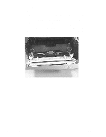
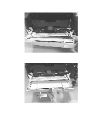
Tray 1 Pickup Roller Removal Be careful not to damage the paper sensor lever while removing the Tray 1 pickup roller. The Tray 1 Pickup Roller Assembly is a field replaceable unit. See "Tray 1 Pickup Roller Assembly Removal" (page 209) for more information. 1 Remove the following assemblies: • Remove the toner cartridge. (See "Toner Cartridge Removal" (page 156) for instructions. • Remove the DIMM cover. (See "DIMM Cover Removal" (page 172) for instructions.) • Remove the rear cover. (See "Rear Cover Removal" (page 177) for instructions.) • Remove the top cover. (See "Top Cover Removal" (page 189) for instructions.) • Remove the left cover. (See "Left Cover Removal" (page 229) for instructions.) • Remove Tray 1. (See "Tray 1 Removal" (page 234) for instructions.) 2 Rotate the left idler roller so that its release mechanism is accessible (see figure 7-115). Figure 7-115Release Mechanism on Idler Roller 3 Press and hold down the separation pad (see figure 7-116). 4 Press and hold the release button, and then slide the idler roller to the left (see figure 7-116). C4170-90959 Parts Removal Tree 237

  • 1
  • 2
  • 3
  • 4
  • 5
  • 6
  • 7
  • 8
  • 9
  • 10
  • 11
  • 12
  • 13
  • 14
  • 15
  • 16
  • 17
  • 18
  • 19
  • 20
  • 21
  • 22
  • 23
  • 24
  • 25
  • 26
  • 27
  • 28
  • 29
  • 30
  • 31
  • 32
  • 33
  • 34
  • 35
  • 36
  • 37
  • 38
  • 39
  • 40
  • 41
  • 42
  • 43
  • 44
  • 45
  • 46
  • 47
  • 48
  • 49
  • 50
  • 51
  • 52
  • 53
  • 54
  • 55
  • 56
  • 57
  • 58
  • 59
  • 60
  • 61
  • 62
  • 63
  • 64
  • 65
  • 66
  • 67
  • 68
  • 69
  • 70
  • 71
  • 72
  • 73
  • 74
  • 75
  • 76
  • 77
  • 78
  • 79
  • 80
  • 81
  • 82
  • 83
  • 84
  • 85
  • 86
  • 87
  • 88
  • 89
  • 90
  • 91
  • 92
  • 93
  • 94
  • 95
  • 96
  • 97
  • 98
  • 99
  • 100
  • 101
  • 102
  • 103
  • 104
  • 105
  • 106
  • 107
  • 108
  • 109
  • 110
  • 111
  • 112
  • 113
  • 114
  • 115
  • 116
  • 117
  • 118
  • 119
  • 120
  • 121
  • 122
  • 123
  • 124
  • 125
  • 126
  • 127
  • 128
  • 129
  • 130
  • 131
  • 132
  • 133
  • 134
  • 135
  • 136
  • 137
  • 138
  • 139
  • 140
  • 141
  • 142
  • 143
  • 144
  • 145
  • 146
  • 147
  • 148
  • 149
  • 150
  • 151
  • 152
  • 153
  • 154
  • 155
  • 156
  • 157
  • 158
  • 159
  • 160
  • 161
  • 162
  • 163
  • 164
  • 165
  • 166
  • 167
  • 168
  • 169
  • 170
  • 171
  • 172
  • 173
  • 174
  • 175
  • 176
  • 177
  • 178
  • 179
  • 180
  • 181
  • 182
  • 183
  • 184
  • 185
  • 186
  • 187
  • 188
  • 189
  • 190
  • 191
  • 192
  • 193
  • 194
  • 195
  • 196
  • 197
  • 198
  • 199
  • 200
  • 201
  • 202
  • 203
  • 204
  • 205
  • 206
  • 207
  • 208
  • 209
  • 210
  • 211
  • 212
  • 213
  • 214
  • 215
  • 216
  • 217
  • 218
  • 219
  • 220
  • 221
  • 222
  • 223
  • 224
  • 225
  • 226
  • 227
  • 228
  • 229
  • 230
  • 231
  • 232
  • 233
  • 234
  • 235
  • 236
  • 237
  • 238
  • 239
  • 240
  • 241
  • 242
  • 243
  • 244
  • 245
  • 246
  • 247
  • 248
  • 249
  • 250
  • 251
  • 252
  • 253
  • 254
  • 255
  • 256
  • 257
  • 258
  • 259
  • 260
  • 261
  • 262
  • 263
  • 264
  • 265
  • 266
  • 267
  • 268
  • 269
  • 270
  • 271
  • 272
  • 273
  • 274
  • 275
  • 276
  • 277
  • 278
  • 279
  • 280
  • 281
  • 282
  • 283
  • 284
  • 285
  • 286
  • 287
  • 288
  • 289
  • 290
  • 291
  • 292
  • 293
  • 294
  • 295
  • 296
  • 297
  • 298
  • 299
  • 300
  • 301
  • 302
  • 303
  • 304
  • 305
  • 306
  • 307
  • 308
  • 309
  • 310

C4170-90959
Parts Removal Tree
237
Tray 1 Pickup Roller Removal
Be careful not to damage the paper sensor lever while removing the Tray 1 pickup roller.
The Tray 1 Pickup Roller Assembly is a field replaceable unit. See “Tray 1 Pickup Roller
Assembly Removal” (page 209) for more information.
1
Remove the following assemblies:
Remove the toner cartridge. (See “Toner Cartridge Removal” (page 156) for
instructions.
Remove the DIMM cover. (See “DIMM Cover Removal” (page 172) for instructions.)
Remove the rear cover. (See “Rear Cover Removal” (page 177) for instructions.)
Remove the top cover. (See “Top Cover Removal” (page189) for instructions.)
Remove the left cover. (See “Left Cover Removal” (page 229) for instructions.)
Remove Tray 1. (See “Tray 1 Removal” (page234) for instructions.)
2
Rotate the left idler roller so that its release mechanism is accessible (see figure 7-115).
Figure 7-115
Release Mechanism on Idler Roller
3
Press and hold down the separation pad (see figure 7-116).
4
Press and hold the release button, and then slide the idler roller to the left (see figure
7-116).