HP 2100 Service Manual - Page 89
Fusing Assembly Control, Power Supply and Control, turned on. This circuit supplies DC voltage +24V
 |
UPC - 873662008284
View all HP 2100 manuals
Add to My Manuals
Save this manual to your list of manuals |
Page 89 highlights
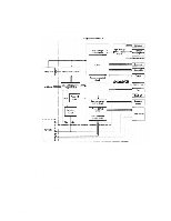
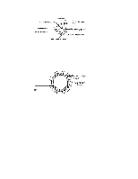
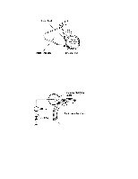
Fusing Assembly Control The fusing assembly's film contains a heater. The Engine Controller Assembly controls the fusing heater during the following temperature modes. See "Sequence of Operation" (page 68) for more information on print period descriptions. • Initial • Print • Between-Page • Postprint The Engine Controller Assembly maintains a temperature of about 195 degrees Celsius (383 degrees Fahrenheit) during print temperature mode. If the fusing system overheats (about 220 degrees Celsius; 428 degrees Fahrenheit), a relay (RL301) opens the power circuit to the fusing heater, causing a Fuser Error message. If the fusing system exceeds about 230 degrees Celsius (446 degrees Fahrenheit), the thermal fuse (FU1131) melts, cutting off power to the fuser assembly. The Engine Controller Assembly monitors the fusing heater temperature via a thermistor (TH701). Power Supply and Control • AC power is supplied to the low-voltage power supply circuit when the power switch is turned on. This circuit supplies DC voltage (+24V, +5V, +3.3V) to the Main Motor, Laser Scanner Unit, Interlock Switch, Video Controller, Solenoids, Paper Feeder, High-Voltage Power Supply, and Formatter. • Opening the top cover interrupts the DC voltage supplied to the high-voltage power supply circuit. • The low-voltage power supply circuit contains an overcurrent/overvoltage protection circuit that automatically turns off the output voltage when an overcurrent condition occurs because of a short or abnormal voltage on the load side. • The protection circuit automatically resets after the input power is turned off then on. The low-voltage power supply circuit also contains a fuse that shuts off the power supply to the circuit when overcurrent conditions occur. See "Engine Control System" (page 77) for more information. In response to the Engine Controller Assembly, the high-voltage power supply circuit (see figure 5-5) supplies DC and AC voltage to the various parts of the Image Formation System. C4170-90959 Engine Control System 79
-
 1
1 -
2
-
3
-
4
-
5
-
6
-
7
-
8
-
9
-
10
-
11
-
12
-
13
-
14
-
15
-
16
-
17
-
18
-
19
-
20
-
21
-
22
-
23
-
24
-
25
-
26
-
27
-
28
-
29
-
30
-
31
-
32
-
33
-
34
-
35
-
36
-
37
-
38
-
39
-
40
-
41
-
42
-
43
-
44
-
45
-
46
-
47
-
48
-
49
-
50
-
51
-
52
-
53
-
54
-
55
-
56
-
57
-
58
-
59
-
60
-
61
-
62
-
63
-
64
-
65
-
66
-
67
-
68
-
69
-
70
-
71
-
72
-
73
-
74
-
75
-
76
-
77
-
78
-
79
-
80
-
81
-
82
-
83
-
 84
84 -
 85
85 -
 86
86 -
 87
87 -
 88
88 -
 89
89 -
 90
90 -
 91
91 -
 92
92 -
 93
93 -
 94
94 -
95
-
96
-
97
-
98
-
99
-
100
-
101
-
102
-
103
-
104
-
105
-
106
-
107
-
108
-
109
-
110
-
111
-
112
-
113
-
114
-
115
-
116
-
117
-
118
-
119
-
120
-
121
-
122
-
123
-
124
-
125
-
126
-
127
-
128
-
129
-
130
-
131
-
132
-
133
-
134
-
135
-
136
-
137
-
138
-
139
-
140
-
141
-
142
-
143
-
144
-
145
-
146
-
147
-
148
-
149
-
150
-
151
-
152
-
153
-
154
-
155
-
156
-
157
-
158
-
159
-
160
-
161
-
162
-
163
-
164
-
165
-
166
-
167
-
168
-
169
-
170
-
171
-
172
-
173
-
174
-
175
-
176
-
177
-
178
-
179
-
180
-
181
-
182
-
183
-
184
-
185
-
186
-
187
-
188
-
189
-
190
-
191
-
192
-
193
-
194
-
195
-
196
-
197
-
198
-
199
-
200
-
201
-
202
-
203
-
204
-
205
-
206
-
207
-
208
-
209
-
210
-
211
-
212
-
213
-
214
-
215
-
216
-
217
-
218
-
219
-
220
-
221
-
222
-
223
-
224
-
225
-
226
-
227
-
228
-
229
-
230
-
231
-
232
-
233
-
234
-
235
-
236
-
237
-
238
-
239
-
240
-
241
-
242
-
243
-
244
-
245
-
246
-
247
-
248
-
249
-
250
-
251
-
252
-
253
-
254
-
255
-
256
-
257
-
258
-
259
-
260
-
261
-
262
-
263
-
264
-
265
-
266
-
267
-
268
-
269
-
270
-
271
-
272
-
273
-
274
-
275
-
276
-
277
-
278
-
279
-
280
-
281
-
282
-
283
-
284
-
285
-
286
-
287
-
288
-
289
-
290
-
291
-
292
-
293
-
294
-
295
-
296
-
297
-
298
-
299
-
300
-
301
-
302
-
303
-
304
-
305
-
306
-
307
-
308
-
309
-
310
 |
 |