HP D530 HP Compaq Business Desktop d500 Service Reference Guide, 5th Edition - Page 127
AGP Card, so that they snap firmly into place.
 |
UPC - 808736649308
View all HP D530 manuals
Add to My Manuals
Save this manual to your list of manuals |
Page 127 highlights
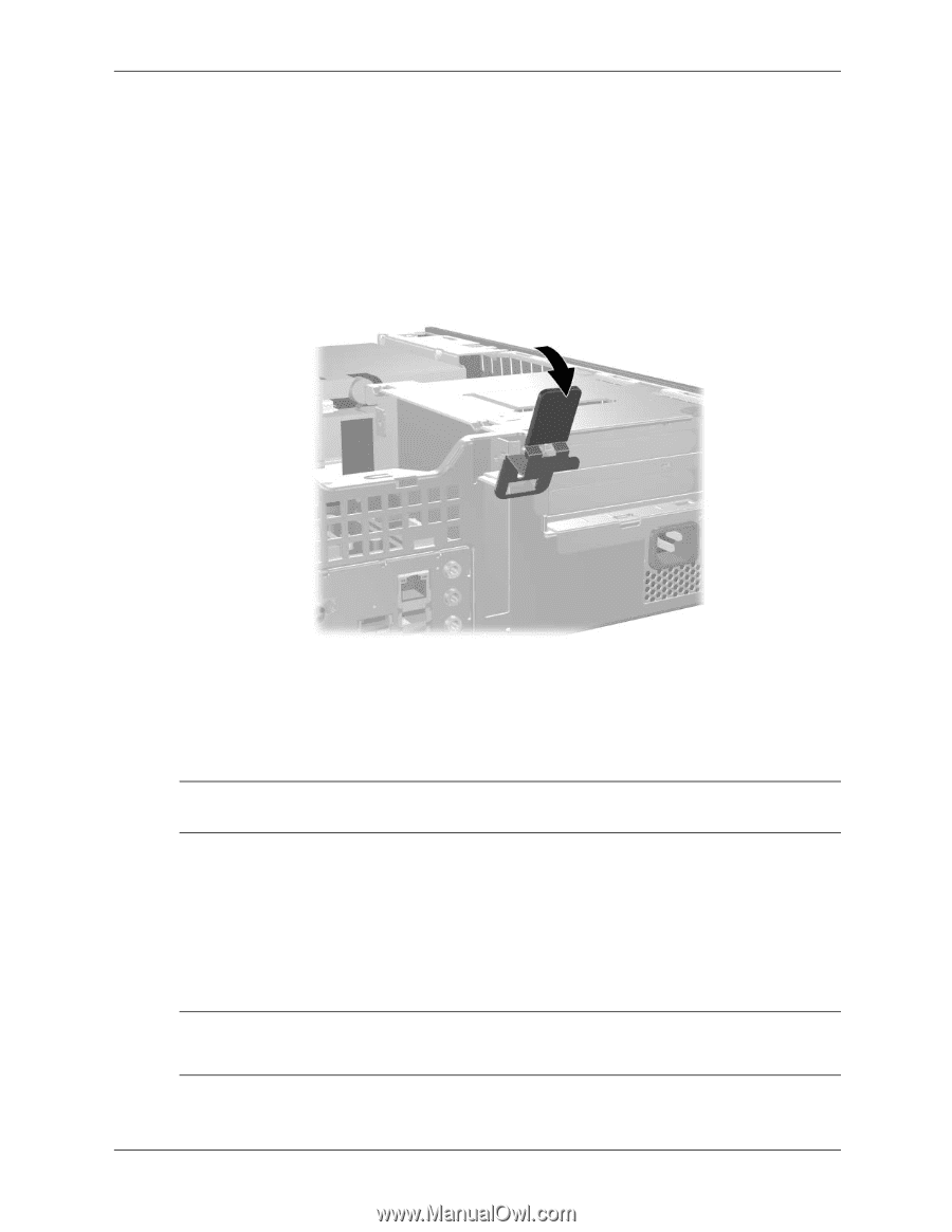
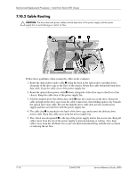
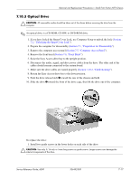
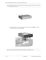
Removal and Replacement Procedures- Small Form Factor (SFF) Chassis 7.9.3 AGP Card 1. If you have locked the Smart Cover Lock, use Computer Setup to unlock the lock (Section 7.2, "Unlocking the Smart Cover Lock"). 2. Prepare the computer for disassembly (Section 7.1, "Preparation for Disassembly"). 3. Remove the computer access panel (Section 7.5, "Computer Access Panel"). 4. Lift the green lever to unlock the AGP card. 5. If installing an AGP card for the first time, go to step 6. If removing an AGP card, go to step 9. 6. Remove the slot cover. 7. Slide the bracket on the end of the expansion card down into the slot on the back of the chassis and press the card down firmly into the socket on the system board. ✎ When you install an expansion card, make sure you press firmly on the card so that the whole connector seats properly in the expansion card socket on the system board. 8. Close the expansion slot retention bracket by rotating it toward the chassis 1 and pressing down on the thumb tabs 2 so that they snap firmly into place. 9. To remove an AGP card, pull the retention arm away from the socket then carefully rock the card back and forth until the connectors pull free from the socket. Lift the expansion card straight up then pull it in toward the center of the chassis to release it from the chassis frame. Be sure not to scrape the card against other components. 10. Store the removed card in anti-static packaging. Ä CAUTION: After removing an expansion card, you must replace it with a new card or cover the open slot (for example, with a metal slot cover or a piece of cardboard taped in place) for proper cooling of internal components during operation. Service Reference Guide, d500 336492-005 7-13
-
 1
1 -
2
-
3
-
4
-
5
-
6
-
7
-
8
-
9
-
10
-
11
-
12
-
13
-
14
-
15
-
16
-
17
-
18
-
19
-
20
-
21
-
22
-
23
-
24
-
25
-
26
-
27
-
28
-
29
-
30
-
31
-
32
-
33
-
34
-
35
-
36
-
37
-
38
-
39
-
40
-
41
-
42
-
43
-
44
-
45
-
46
-
47
-
48
-
49
-
50
-
51
-
52
-
53
-
54
-
55
-
56
-
57
-
58
-
59
-
60
-
61
-
62
-
63
-
64
-
65
-
66
-
67
-
68
-
69
-
70
-
71
-
72
-
73
-
74
-
75
-
76
-
77
-
78
-
79
-
80
-
81
-
82
-
83
-
84
-
85
-
86
-
87
-
88
-
89
-
90
-
91
-
92
-
93
-
94
-
95
-
96
-
97
-
98
-
99
-
100
-
101
-
102
-
103
-
104
-
105
-
106
-
107
-
108
-
109
-
110
-
111
-
112
-
113
-
114
-
115
-
116
-
117
-
118
-
119
-
120
-
121
-
 122
122 -
 123
123 -
 124
124 -
 125
125 -
 126
126 -
 127
127 -
 128
128 -
 129
129 -
 130
130 -
 131
131 -
 132
132 -
133
-
134
-
135
-
136
-
137
-
138
-
139
-
140
-
141
-
142
-
143
-
144
-
145
-
146
-
147
-
148
-
149
-
150
-
151
-
152
-
153
-
154
-
155
-
156
-
157
-
158
-
159
-
160
-
161
-
162
-
163
-
164
-
165
-
166
-
167
-
168
-
169
-
170
-
171
-
172
-
173
-
174
-
175
-
176
-
177
-
178
-
179
-
180
-
181
-
182
-
183
-
184
-
185
-
186
-
187
-
188
-
189
-
190
-
191
-
192
-
193
-
194
-
195
-
196
-
197
-
198
-
199
-
200
-
201
-
202
-
203
-
204
-
205
-
206
-
207
-
208
-
209
-
210
-
211
-
212
-
213
-
214
-
215
-
216
-
217
-
218
-
219
-
220
-
221
-
222
-
223
-
224
-
225
-
226
-
227
-
228
-
229
-
230
-
231
-
232
-
233
-
234
 |
 |