HP D530 HP Compaq Business Desktop d500 Service Reference Guide, 5th Edition - Page 163
Front Chassis Panel, Preparation for Disassembly, Top Access Panel, System Fan
 |
UPC - 808736649308
View all HP D530 manuals
Add to My Manuals
Save this manual to your list of manuals |
Page 163 highlights
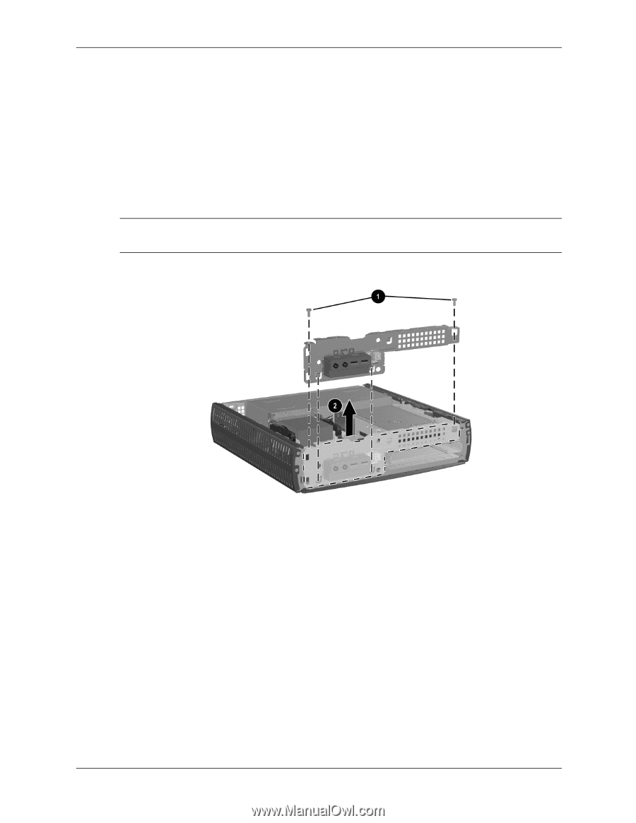
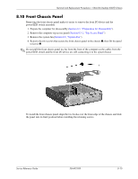
Removal and Replacement Procedures- Ultra-Slim Desktop (USDT) Chassis 8.10 Front Chassis Panel Removing the front chassis panel makes it easier to remove the front I/O device and the power/LED switch assembly. 1. Prepare the computer for disassembly (Section 8.1, "Preparation for Disassembly"). 2. Remove the computer top access panel (Section 8.3.1, "Top Access Panel"). 3. Remove the system fan (Section 8.9, "System Fan"). 4. Remove the two screws that secure the front chassis panel to the chassis 1, then lift the panel to free it 2. ✎ Do not pull the front chassis panel too far from the front of the computer as the cables from the power/LED switch and the front I/O device are still connecting it to the system board. To install the front chassis panel, align the two hooks over the front edge of the chassis and slide the panel into its final position before installing the retaining screws. Service Reference Guide 336492-005 8-15
-
 1
1 -
2
-
3
-
4
-
5
-
6
-
7
-
8
-
9
-
10
-
11
-
12
-
13
-
14
-
15
-
16
-
17
-
18
-
19
-
20
-
21
-
22
-
23
-
24
-
25
-
26
-
27
-
28
-
29
-
30
-
31
-
32
-
33
-
34
-
35
-
36
-
37
-
38
-
39
-
40
-
41
-
42
-
43
-
44
-
45
-
46
-
47
-
48
-
49
-
50
-
51
-
52
-
53
-
54
-
55
-
56
-
57
-
58
-
59
-
60
-
61
-
62
-
63
-
64
-
65
-
66
-
67
-
68
-
69
-
70
-
71
-
72
-
73
-
74
-
75
-
76
-
77
-
78
-
79
-
80
-
81
-
82
-
83
-
84
-
85
-
86
-
87
-
88
-
89
-
90
-
91
-
92
-
93
-
94
-
95
-
96
-
97
-
98
-
99
-
100
-
101
-
102
-
103
-
104
-
105
-
106
-
107
-
108
-
109
-
110
-
111
-
112
-
113
-
114
-
115
-
116
-
117
-
118
-
119
-
120
-
121
-
122
-
123
-
124
-
125
-
126
-
127
-
128
-
129
-
130
-
131
-
132
-
133
-
134
-
135
-
136
-
137
-
138
-
139
-
140
-
141
-
142
-
143
-
144
-
145
-
146
-
147
-
148
-
149
-
150
-
151
-
152
-
153
-
154
-
155
-
156
-
157
-
 158
158 -
 159
159 -
 160
160 -
 161
161 -
 162
162 -
 163
163 -
 164
164 -
 165
165 -
 166
166 -
 167
167 -
 168
168 -
169
-
170
-
171
-
172
-
173
-
174
-
175
-
176
-
177
-
178
-
179
-
180
-
181
-
182
-
183
-
184
-
185
-
186
-
187
-
188
-
189
-
190
-
191
-
192
-
193
-
194
-
195
-
196
-
197
-
198
-
199
-
200
-
201
-
202
-
203
-
204
-
205
-
206
-
207
-
208
-
209
-
210
-
211
-
212
-
213
-
214
-
215
-
216
-
217
-
218
-
219
-
220
-
221
-
222
-
223
-
224
-
225
-
226
-
227
-
228
-
229
-
230
-
231
-
232
-
233
-
234
 |
 |