HP D530 HP Compaq Business Desktop d500 Service Reference Guide, 5th Edition - Page 147
Power Supply
 |
UPC - 808736649308
View all HP D530 manuals
Add to My Manuals
Save this manual to your list of manuals |
Page 147 highlights
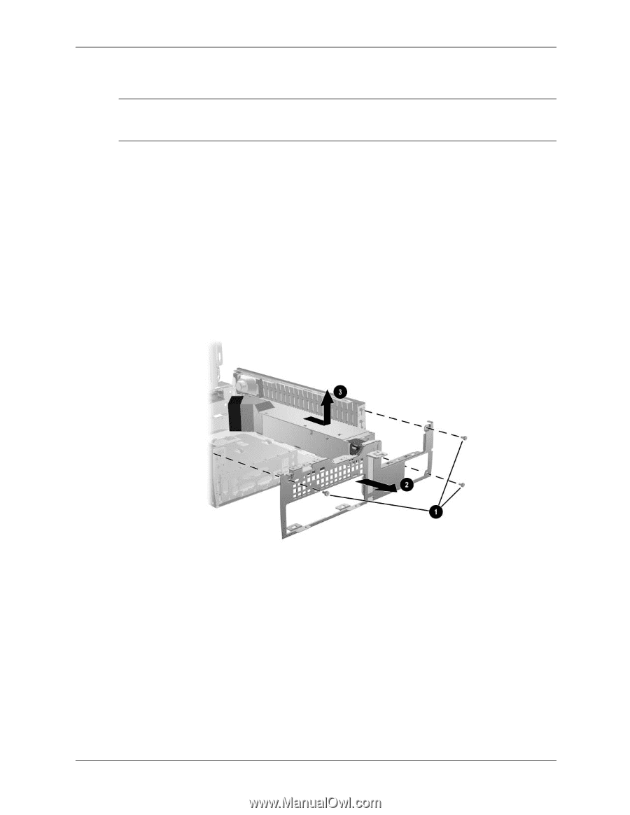
Removal and Replacement Procedures- Small Form Factor (SFF) Chassis 7.18 Power Supply Å WARNING: Voltage is always present on the system board when the computer is plugged into an active AC outlet. To avoid possible personal injury and damage to the equipment the power cord should be disconnected from the computer and/or the AC outlet before opening the computer. 1. Prepare the computer for disassembly (Section 7.1, "Preparation for Disassembly"). 2. Remove the computer access panel (Section 7.5, "Computer Access Panel"). 3. Rotate the drive cage to its upright position. 4. Remove the expansion card cage (Section 7.9, "Expansion Card Cage"). 5. Carefully cut the cable tie that secures the power supply cable bundle to the power switch cable, the speaker cable, and the front I/O cable. 6. Disconnect all power cables from the mass storage devices and from the system board. 7. Remove the three screws that secure the rear chassis panel to the chassis 1, the pull the rear chassis panel straight back 2 to remove it from the chassis. 8. Slide the power supply out the back of the computer 3. To install the power supply, reverse the removal procedure. Service Reference Guide, d500 336492-005 7-33
-
 1
1 -
2
-
3
-
4
-
5
-
6
-
7
-
8
-
9
-
10
-
11
-
12
-
13
-
14
-
15
-
16
-
17
-
18
-
19
-
20
-
21
-
22
-
23
-
24
-
25
-
26
-
27
-
28
-
29
-
30
-
31
-
32
-
33
-
34
-
35
-
36
-
37
-
38
-
39
-
40
-
41
-
42
-
43
-
44
-
45
-
46
-
47
-
48
-
49
-
50
-
51
-
52
-
53
-
54
-
55
-
56
-
57
-
58
-
59
-
60
-
61
-
62
-
63
-
64
-
65
-
66
-
67
-
68
-
69
-
70
-
71
-
72
-
73
-
74
-
75
-
76
-
77
-
78
-
79
-
80
-
81
-
82
-
83
-
84
-
85
-
86
-
87
-
88
-
89
-
90
-
91
-
92
-
93
-
94
-
95
-
96
-
97
-
98
-
99
-
100
-
101
-
102
-
103
-
104
-
105
-
106
-
107
-
108
-
109
-
110
-
111
-
112
-
113
-
114
-
115
-
116
-
117
-
118
-
119
-
120
-
121
-
122
-
123
-
124
-
125
-
126
-
127
-
128
-
129
-
130
-
131
-
132
-
133
-
134
-
135
-
136
-
137
-
138
-
139
-
140
-
141
-
 142
142 -
 143
143 -
 144
144 -
 145
145 -
 146
146 -
 147
147 -
 148
148 -
 149
149 -
 150
150 -
 151
151 -
 152
152 -
153
-
154
-
155
-
156
-
157
-
158
-
159
-
160
-
161
-
162
-
163
-
164
-
165
-
166
-
167
-
168
-
169
-
170
-
171
-
172
-
173
-
174
-
175
-
176
-
177
-
178
-
179
-
180
-
181
-
182
-
183
-
184
-
185
-
186
-
187
-
188
-
189
-
190
-
191
-
192
-
193
-
194
-
195
-
196
-
197
-
198
-
199
-
200
-
201
-
202
-
203
-
204
-
205
-
206
-
207
-
208
-
209
-
210
-
211
-
212
-
213
-
214
-
215
-
216
-
217
-
218
-
219
-
220
-
221
-
222
-
223
-
224
-
225
-
226
-
227
-
228
-
229
-
230
-
231
-
232
-
233
-
234
 |
 |