HP D530 HP Compaq Business Desktop d500 Service Reference Guide, 5th Edition - Page 167
Power Supply
 |
UPC - 808736649308
View all HP D530 manuals
Add to My Manuals
Save this manual to your list of manuals |
Page 167 highlights
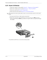
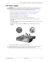
Removal and Replacement Procedures- Ultra-Slim Desktop (USDT) Chassis 8.14 Power Supply Å WARNING: Voltage is always present on the system board when the computer is plugged into an active AC outlet. To avoid possible personal injury and damage to the equipment the power cord should be disconnected from the computer and/or the AC outlet before opening the computer. 1. Prepare the computer for disassembly (Section 8.1, "Preparation for Disassembly"). 2. Remove the computer top access panel (Section 8.3.1, "Top Access Panel"). 3. Remove the system fan (Section 8.9, "System Fan"). 4. Remove the hard drive (Section 8.8.1, "Hard Drive"). 5. Disconnect the three power cable connectors from the system board. 6. Rotate the green retaining latch in a counterclockwise direction to release the power supply 1. 7. Slide the power supply toward the front of the computer 2, making sure the keyhole latch on the left side is clear. 8. Lift the power supply from the chassis 3 making sure that the cables do not snag on anything. To install the power supply, reverse the removal procedure. ✎ When installing the power supply make sure the three cables are routed properly and do not interfere with the heatsink, the fan assembly, or the hard drive release latch. Service Reference Guide 336492-005 8-19
-
 1
1 -
2
-
3
-
4
-
5
-
6
-
7
-
8
-
9
-
10
-
11
-
12
-
13
-
14
-
15
-
16
-
17
-
18
-
19
-
20
-
21
-
22
-
23
-
24
-
25
-
26
-
27
-
28
-
29
-
30
-
31
-
32
-
33
-
34
-
35
-
36
-
37
-
38
-
39
-
40
-
41
-
42
-
43
-
44
-
45
-
46
-
47
-
48
-
49
-
50
-
51
-
52
-
53
-
54
-
55
-
56
-
57
-
58
-
59
-
60
-
61
-
62
-
63
-
64
-
65
-
66
-
67
-
68
-
69
-
70
-
71
-
72
-
73
-
74
-
75
-
76
-
77
-
78
-
79
-
80
-
81
-
82
-
83
-
84
-
85
-
86
-
87
-
88
-
89
-
90
-
91
-
92
-
93
-
94
-
95
-
96
-
97
-
98
-
99
-
100
-
101
-
102
-
103
-
104
-
105
-
106
-
107
-
108
-
109
-
110
-
111
-
112
-
113
-
114
-
115
-
116
-
117
-
118
-
119
-
120
-
121
-
122
-
123
-
124
-
125
-
126
-
127
-
128
-
129
-
130
-
131
-
132
-
133
-
134
-
135
-
136
-
137
-
138
-
139
-
140
-
141
-
142
-
143
-
144
-
145
-
146
-
147
-
148
-
149
-
150
-
151
-
152
-
153
-
154
-
155
-
156
-
157
-
158
-
159
-
160
-
161
-
 162
162 -
 163
163 -
 164
164 -
 165
165 -
 166
166 -
 167
167 -
 168
168 -
 169
169 -
 170
170 -
 171
171 -
 172
172 -
173
-
174
-
175
-
176
-
177
-
178
-
179
-
180
-
181
-
182
-
183
-
184
-
185
-
186
-
187
-
188
-
189
-
190
-
191
-
192
-
193
-
194
-
195
-
196
-
197
-
198
-
199
-
200
-
201
-
202
-
203
-
204
-
205
-
206
-
207
-
208
-
209
-
210
-
211
-
212
-
213
-
214
-
215
-
216
-
217
-
218
-
219
-
220
-
221
-
222
-
223
-
224
-
225
-
226
-
227
-
228
-
229
-
230
-
231
-
232
-
233
-
234
 |
 |