HP D530 HP Compaq Business Desktop d500 Service Reference Guide, 5th Edition - Page 171
Drive Cage Assembly, Front I/O Device
 |
UPC - 808736649308
View all HP D530 manuals
Add to My Manuals
Save this manual to your list of manuals |
Page 171 highlights
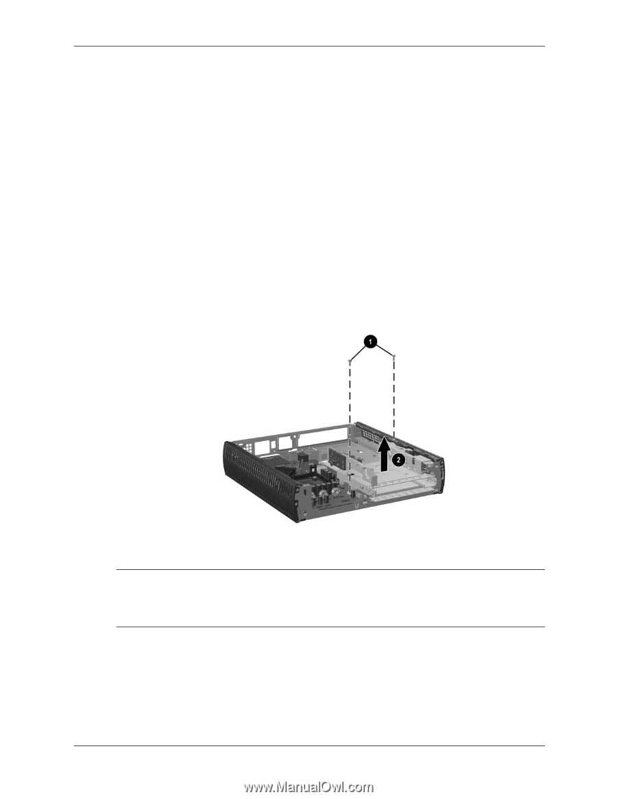
Removal and Replacement Procedures- Ultra-Slim Desktop (USDT) Chassis 8.16 Drive Cage Assembly 1. Prepare the computer for disassembly (Section 8.1, "Preparation for Disassembly"). 2. Remove the computer top access panel (Section 8.3.1, "Top Access Panel"). 3. Remove the hard drive (Section 8.8.1, "Hard Drive"). 4. Remove the system fan (Section 8.9, "System Fan"). 5. Remove the front chassis panel (Section 8.10, "Front Chassis Panel"). 6. Disconnect the power switch cable from the system board (Section 8.12, "Power Switch Assembly"). 7. Disconnect the front I/O cable from the system board (Section 8.11, "Front I/O Device"). 8. Remove the power supply (Section 8.14, "Power Supply"). 9. Remove the two screws that secure the drive cage to the chassis 1. 10. Pull up evenly on the drive cage 2 to disengage the MultiBay connector card from the system board and to release the cage from the chassis. To install the drive cage, reverse the removal procedures. ✎ Make sure the eject lever is in its rear-most position before installing the drive cage. Test the action of the eject lever before installing the retaining screws. Make sure that the 9 mm long screw is used to secure the foot of the drive cage thru the system board. Service Reference Guide 336492-005 8-23
-
 1
1 -
2
-
3
-
4
-
5
-
6
-
7
-
8
-
9
-
10
-
11
-
12
-
13
-
14
-
15
-
16
-
17
-
18
-
19
-
20
-
21
-
22
-
23
-
24
-
25
-
26
-
27
-
28
-
29
-
30
-
31
-
32
-
33
-
34
-
35
-
36
-
37
-
38
-
39
-
40
-
41
-
42
-
43
-
44
-
45
-
46
-
47
-
48
-
49
-
50
-
51
-
52
-
53
-
54
-
55
-
56
-
57
-
58
-
59
-
60
-
61
-
62
-
63
-
64
-
65
-
66
-
67
-
68
-
69
-
70
-
71
-
72
-
73
-
74
-
75
-
76
-
77
-
78
-
79
-
80
-
81
-
82
-
83
-
84
-
85
-
86
-
87
-
88
-
89
-
90
-
91
-
92
-
93
-
94
-
95
-
96
-
97
-
98
-
99
-
100
-
101
-
102
-
103
-
104
-
105
-
106
-
107
-
108
-
109
-
110
-
111
-
112
-
113
-
114
-
115
-
116
-
117
-
118
-
119
-
120
-
121
-
122
-
123
-
124
-
125
-
126
-
127
-
128
-
129
-
130
-
131
-
132
-
133
-
134
-
135
-
136
-
137
-
138
-
139
-
140
-
141
-
142
-
143
-
144
-
145
-
146
-
147
-
148
-
149
-
150
-
151
-
152
-
153
-
154
-
155
-
156
-
157
-
158
-
159
-
160
-
161
-
162
-
163
-
164
-
165
-
 166
166 -
 167
167 -
 168
168 -
 169
169 -
 170
170 -
 171
171 -
 172
172 -
 173
173 -
 174
174 -
 175
175 -
 176
176 -
177
-
178
-
179
-
180
-
181
-
182
-
183
-
184
-
185
-
186
-
187
-
188
-
189
-
190
-
191
-
192
-
193
-
194
-
195
-
196
-
197
-
198
-
199
-
200
-
201
-
202
-
203
-
204
-
205
-
206
-
207
-
208
-
209
-
210
-
211
-
212
-
213
-
214
-
215
-
216
-
217
-
218
-
219
-
220
-
221
-
222
-
223
-
224
-
225
-
226
-
227
-
228
-
229
-
230
-
231
-
232
-
233
-
234
 |
 |