HP D530 HP Compaq Business Desktop d500 Service Reference Guide, 5th Edition - Page 97
Power Switch Assembly
 |
UPC - 808736649308
View all HP D530 manuals
Add to My Manuals
Save this manual to your list of manuals |
Page 97 highlights
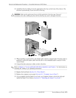
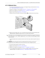
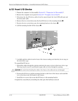
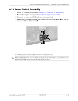
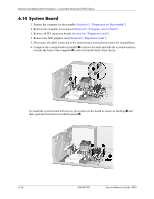
Removal and Replacement Procedures- Convertible Minitower (CMT) Chassis 6.13 Power Switch Assembly 1. Prepare the computer for disassembly (Section 6.1, "Preparation for Disassembly"). 2. Remove the computer access panel (Section 6.5, "Computer Access Panel"). 3. Disconnect the power switch/LED cable from the system board. 4. Squeeze the switch holder retaining clips together at the front of the chassis 1 and push the switch assembly out of the chassis 2. To install the power switch assembly, reverse the removal procedure. ✎ When installing the power switch cable it may be necessary to disconnect a data cabe from one of the drives to make it easier to grab the free end of the cable. Service Reference Guide, d500 336492-005 6-25
-
 1
1 -
2
-
3
-
4
-
5
-
6
-
7
-
8
-
9
-
10
-
11
-
12
-
13
-
14
-
15
-
16
-
17
-
18
-
19
-
20
-
21
-
22
-
23
-
24
-
25
-
26
-
27
-
28
-
29
-
30
-
31
-
32
-
33
-
34
-
35
-
36
-
37
-
38
-
39
-
40
-
41
-
42
-
43
-
44
-
45
-
46
-
47
-
48
-
49
-
50
-
51
-
52
-
53
-
54
-
55
-
56
-
57
-
58
-
59
-
60
-
61
-
62
-
63
-
64
-
65
-
66
-
67
-
68
-
69
-
70
-
71
-
72
-
73
-
74
-
75
-
76
-
77
-
78
-
79
-
80
-
81
-
82
-
83
-
84
-
85
-
86
-
87
-
88
-
89
-
90
-
91
-
 92
92 -
 93
93 -
 94
94 -
 95
95 -
 96
96 -
 97
97 -
 98
98 -
 99
99 -
 100
100 -
 101
101 -
 102
102 -
103
-
104
-
105
-
106
-
107
-
108
-
109
-
110
-
111
-
112
-
113
-
114
-
115
-
116
-
117
-
118
-
119
-
120
-
121
-
122
-
123
-
124
-
125
-
126
-
127
-
128
-
129
-
130
-
131
-
132
-
133
-
134
-
135
-
136
-
137
-
138
-
139
-
140
-
141
-
142
-
143
-
144
-
145
-
146
-
147
-
148
-
149
-
150
-
151
-
152
-
153
-
154
-
155
-
156
-
157
-
158
-
159
-
160
-
161
-
162
-
163
-
164
-
165
-
166
-
167
-
168
-
169
-
170
-
171
-
172
-
173
-
174
-
175
-
176
-
177
-
178
-
179
-
180
-
181
-
182
-
183
-
184
-
185
-
186
-
187
-
188
-
189
-
190
-
191
-
192
-
193
-
194
-
195
-
196
-
197
-
198
-
199
-
200
-
201
-
202
-
203
-
204
-
205
-
206
-
207
-
208
-
209
-
210
-
211
-
212
-
213
-
214
-
215
-
216
-
217
-
218
-
219
-
220
-
221
-
222
-
223
-
224
-
225
-
226
-
227
-
228
-
229
-
230
-
231
-
232
-
233
-
234
 |
 |
Service Reference Guide, d500
336492-005
6–25
Removal and Replacement Procedures— Convertible Minitower (CMT) Chassis
6.13 Power Switch Assembly
1. Prepare the computer for disassembly (
Section 6.1, “Preparation for Disassembly”
).
2. Remove the computer access panel (
Section 6.5, “Computer Access Panel”
).
3. Disconnect the power switch/LED cable from the system board.
4. Squeeze the switch holder retaining clips together at the front of the chassis
1
and push the
switch assembly out of the chassis
2
.
To install the power switch assembly, reverse the removal procedure.
✎
When installing the power switch cable it may be necessary to disconnect a data cabe from one
of the drives to make it easier to grab the free end of the cable.