HP D530 HP Compaq Business Desktop d500 Service Reference Guide, 5th Edition - Page 139
Power Switch Assembly
 |
UPC - 808736649308
View all HP D530 manuals
Add to My Manuals
Save this manual to your list of manuals |
Page 139 highlights
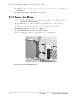
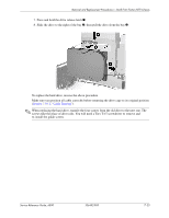
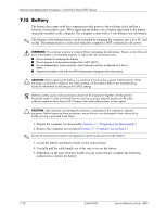
Removal and Replacement Procedures- Small Form Factor (SFF) Chassis 7.12 Power Switch Assembly 1. Prepare the computer for disassembly (Section 7.1, "Preparation for Disassembly"). 2. Remove the computer access panel (Section 7.5, "Computer Access Panel"). 3. Disconnect the power switch/LED cable from the system board. 4. Carefully cut the cable tie that secures the power switch cable to the power supply cable cable bundle. Ä CAUTION: Be careful when cutting the cable tie not to cut any cables. 5. Squeeze the switch holder retaining clips together at the front of the chassis 1 and push the switch assembly out of the chassis 2. To install the power switch assembly, reverse the removal procedure. Service Reference Guide, d500 336492-005 7-25
-
 1
1 -
2
-
3
-
4
-
5
-
6
-
7
-
8
-
9
-
10
-
11
-
12
-
13
-
14
-
15
-
16
-
17
-
18
-
19
-
20
-
21
-
22
-
23
-
24
-
25
-
26
-
27
-
28
-
29
-
30
-
31
-
32
-
33
-
34
-
35
-
36
-
37
-
38
-
39
-
40
-
41
-
42
-
43
-
44
-
45
-
46
-
47
-
48
-
49
-
50
-
51
-
52
-
53
-
54
-
55
-
56
-
57
-
58
-
59
-
60
-
61
-
62
-
63
-
64
-
65
-
66
-
67
-
68
-
69
-
70
-
71
-
72
-
73
-
74
-
75
-
76
-
77
-
78
-
79
-
80
-
81
-
82
-
83
-
84
-
85
-
86
-
87
-
88
-
89
-
90
-
91
-
92
-
93
-
94
-
95
-
96
-
97
-
98
-
99
-
100
-
101
-
102
-
103
-
104
-
105
-
106
-
107
-
108
-
109
-
110
-
111
-
112
-
113
-
114
-
115
-
116
-
117
-
118
-
119
-
120
-
121
-
122
-
123
-
124
-
125
-
126
-
127
-
128
-
129
-
130
-
131
-
132
-
133
-
 134
134 -
 135
135 -
 136
136 -
 137
137 -
 138
138 -
 139
139 -
 140
140 -
 141
141 -
 142
142 -
 143
143 -
 144
144 -
145
-
146
-
147
-
148
-
149
-
150
-
151
-
152
-
153
-
154
-
155
-
156
-
157
-
158
-
159
-
160
-
161
-
162
-
163
-
164
-
165
-
166
-
167
-
168
-
169
-
170
-
171
-
172
-
173
-
174
-
175
-
176
-
177
-
178
-
179
-
180
-
181
-
182
-
183
-
184
-
185
-
186
-
187
-
188
-
189
-
190
-
191
-
192
-
193
-
194
-
195
-
196
-
197
-
198
-
199
-
200
-
201
-
202
-
203
-
204
-
205
-
206
-
207
-
208
-
209
-
210
-
211
-
212
-
213
-
214
-
215
-
216
-
217
-
218
-
219
-
220
-
221
-
222
-
223
-
224
-
225
-
226
-
227
-
228
-
229
-
230
-
231
-
232
-
233
-
234
 |
 |
Service Reference Guide, d500
336492-005
7–25
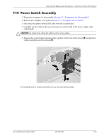
Removal and Replacement Procedures— Small Form Factor (SFF) Chassis
7.12 Power Switch Assembly
1. Prepare the computer for disassembly (
Section 7.1, “Preparation for Disassembly”
).
2. Remove the computer access panel (
Section 7.5, “Computer Access Panel”
).
3. Disconnect the power switch/LED cable from the system board.
4. Carefully cut the cable tie that secures the power switch cable to the power supply cable
cable bundle.
Ä
CAUTION:
Be careful when cutting the cable tie not to cut any cables.
5. Squeeze the switch holder retaining clips together at the front of the chassis
1
and push the
switch assembly out of the chassis
2
.
To install the power switch assembly, reverse the removal procedure.