HP D530 HP Compaq Business Desktop d500 Service Reference Guide, 5th Edition - Page 227
Index
 |
UPC - 808736649308
View all HP D530 manuals
Add to My Manuals
Save this manual to your list of manuals |
Page 227 highlights
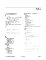
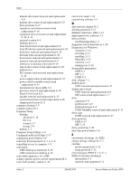
Index 4-pin power pin assignments A-8 20-pin power pin assignments A-8 A access panel bottom, USDT removal and replacement 8-5 CMT removal and replacement 6-5 top, USDT removal and replacement 8-4 access to computer, controlling 3-8 advanced, Computer Setup heading 2-10 AGP card pin assignments A-7 asset tracking 3-8 ATA/ATAPI (IDE) drive cable pin assignments A-6 B battery CMT removal and replacement 6-27 disposal 5-8 real-time clock D-2 SFF removal and replacement 7-28 USDT removal and replacement 8-20 blank screen D-9 bootable disk, important information 3-19 C cable CMT hard drive 6-18 proper handling 5-8 SFF hard drive 7-22 SFF optical drive 7-19 USDT hard drive 8-12 cable layout, PATA 4-3 cable lock CMT 6-4 SFF 7-4 USDT 8-2 cable lock provision 3-19 cable pinouts PATA data 4-2 PATA power 4-2 SATA data 4-1 SATA power 4-2 categories, Diagnostics for Windows 2-14 cautions AC power 5-1 adding devices 1-1 batteries 5-8 cables 5-8 cooling fan 5-7 cover lock security 3-16 FailSafe Key 3-17 keyboard cleaning 5-6 keyboard keys 5-6 operating system installation 1-1 protecting ROM 3-4 changing operating systems, important information 3-7 changing password 3-13 chassis CMT illustrated 5-1 SFF illustrated 5-2 USDT illustrated 5-2 chassis fan CMT removal and replacement 6-34 SFF removal and replacement 7-27 USDT removal and replacement 8-25 chassis types, illustrated 5-1 cleaning computer 5-5 keyboard 5-6 monitor 5-6 mouse 5-6 clearing password 3-14 cloning tools, software 3-1 CMT 5.25" drive bezel removal and replacement 6-7 access panel removal and replacement 6-5 AGP card removal and replacement 6-12 battery removal and replacement 6-27 cable lock 6-4 chassis fan removal and replacement 6-34 chassis, illustrated 5-1 desktop to minitower conversion 6-36 disassembly preparation 6-1 Service Reference Guide, d500 336492-005 Index-1
-
 1
1 -
2
-
3
-
4
-
5
-
6
-
7
-
8
-
9
-
10
-
11
-
12
-
13
-
14
-
15
-
16
-
17
-
18
-
19
-
20
-
21
-
22
-
23
-
24
-
25
-
26
-
27
-
28
-
29
-
30
-
31
-
32
-
33
-
34
-
35
-
36
-
37
-
38
-
39
-
40
-
41
-
42
-
43
-
44
-
45
-
46
-
47
-
48
-
49
-
50
-
51
-
52
-
53
-
54
-
55
-
56
-
57
-
58
-
59
-
60
-
61
-
62
-
63
-
64
-
65
-
66
-
67
-
68
-
69
-
70
-
71
-
72
-
73
-
74
-
75
-
76
-
77
-
78
-
79
-
80
-
81
-
82
-
83
-
84
-
85
-
86
-
87
-
88
-
89
-
90
-
91
-
92
-
93
-
94
-
95
-
96
-
97
-
98
-
99
-
100
-
101
-
102
-
103
-
104
-
105
-
106
-
107
-
108
-
109
-
110
-
111
-
112
-
113
-
114
-
115
-
116
-
117
-
118
-
119
-
120
-
121
-
122
-
123
-
124
-
125
-
126
-
127
-
128
-
129
-
130
-
131
-
132
-
133
-
134
-
135
-
136
-
137
-
138
-
139
-
140
-
141
-
142
-
143
-
144
-
145
-
146
-
147
-
148
-
149
-
150
-
151
-
152
-
153
-
154
-
155
-
156
-
157
-
158
-
159
-
160
-
161
-
162
-
163
-
164
-
165
-
166
-
167
-
168
-
169
-
170
-
171
-
172
-
173
-
174
-
175
-
176
-
177
-
178
-
179
-
180
-
181
-
182
-
183
-
184
-
185
-
186
-
187
-
188
-
189
-
190
-
191
-
192
-
193
-
194
-
195
-
196
-
197
-
198
-
199
-
200
-
201
-
202
-
203
-
204
-
205
-
206
-
207
-
208
-
209
-
210
-
211
-
212
-
213
-
214
-
215
-
216
-
217
-
218
-
219
-
220
-
221
-
 222
222 -
 223
223 -
 224
224 -
 225
225 -
 226
226 -
 227
227 -
 228
228 -
 229
229 -
 230
230 -
 231
231 -
 232
232 -
233
-
234
 |
 |